Copyright © 1997-2001 Jungo Ltd. All Rights Reserved
Information in this document is subject to change without notice. The software described in this document is furnished under a license agreement. The software may be used, copied or distributed only in accordance with that agreement. No part of this publication may be reproduced, stored in a retrieval system, or transmitted in any form or any means, electronically or mechanical, including photocopying and recording for any purpose without the written permission of Jungo Ltd.
Windows, Win32, Windows 95, Windows 98, Windows ME, Windows CE, Windows NT and Windows 2000 are trademarks of Microsoft Corp. WinDriver and KernelDriver are trademarks of Jungo. Other brand and product names are trademarks or registered trademarks of their respective holders.
2.1 USB Endpoints
2.2 USB Pipes
2.3 WinDriver USB Architecture
4.1 Selection of PnP Device
4.2 USB Device Configuration
4.3 A PCI Diagnostics Screen
4.4 USB Diagnostics Screen
4.5 Generate Code Option
4.6 Select Driver Type
4.7 Options for Generating Code
4.8 Remote WinDriver on all Windows OS
4.9 Remote WinDriver on Windows CE
4.10 Remote WinDriver on Linux
6.1 Start DebugMonitor
6.2 Set Trace Options
10.1 USB Data Exchange
10.2 USB Read and Write
13.1 KernelPlugIn Architecture
14.1 Interrupt Handling without Kernel PlugIn
14.2 Interrupt Handling with the Kernel PlugIn
In this Chapter you will explore the uses of WinDriver, and learn the basic steps of creating your driver.
WinDriver is a device driver development toolkit that dramatically simplifies the very difficult task of developing a device driver. The driver you develop using WinDriver is source code compatible between all supported operating systems (WinDriver currently supports Windows 95/98/ME/NT/2000/CE, Linux, Solaris, VxWorks and OS/2.). It is binary compatible between Windows 95, 98, ME, NT and 2000. Bus architecture support includes PCI/PCMCIA/ ISA/ISA PnP/EISA/CompactPCI and USB. WinDriver provides a complete solution for creating high performance drivers, which handle interrupts and I/O at optimal rates.
Don't let the size of this manual fool you - WinDriver makes developing device drivers an easy task that takes hours instead of months. Most developers will find that reading this chapter and glancing through the DriverWizard and function reference chapters is all they need to successfully write their driver.
The major part of this manual deals with the features that WinDriver offers to the advanced user.
WinDriver supports all PCI bridges, from all vendors. Enhanced support is offered for the PLX / Altera / Galileo / QuickLogic / PLDA / AMCC and V3 PCI chips. A special chapter is dedicated to developers of PCI card drivers who are using PCI chips from these vendors. The last several chapters of this manual explain how to tune your driver code to achieve optimal performance. The ``Kernel PlugIn'' feature of WinDriver is explained there. This feature allows the developer to write and debug the entire device driver in the User Mode, and later `drop' performance critical parts of it into the Kernel Mode. Therefore, the driver achieves optimal Kernel Mode performance, with User Mode ease of use.
Please check Jungo's web site at http://www.jungo.com for the latest news about WinDriver and other driver development tools that Jungo offers.
Good luck with your project!
In protected operating systems (such as Windows, Linux, Solaris and OS/2), a programmer cannot access hardware directly from the application level (the ``User Mode'') where development work is usually done. Hardware access is allowed only from within the operating system itself (the ``Kernel Mode'' or ``Ring 0''), by software modules called ``Device Drivers''. In order to access a custom hardware device from the application level, a programmer must do the following:
Easy development - WinDriver enables Windows programmers to create PCI/PCMCIA/ISA/ISA PnP/EISA/CompactPCI and USB based device drivers in an extremely short time. WinDriver allows you to create your driver in the ``User Mode'' in the familiar environment - using MSDEV, Visual C/C++, Borland Delphi, Borland C++, Visual Basic, GCC or any other 32-bit compiler. WinDriver eliminates the need for you to be familiar with the operating system internals, kernel programming or with the DDK,ETK,DDI/DKI or have any device driver knowledge.
Cross Platform - The driver created with WinDriver will run on Windows 95/ 98/ME/NT/2000/CE, Linux, Solaris, VxWorks and OS/2, - i.e. write once - run on any of these platforms.
Friendly Wizards - DriverWizard (included) is a graphical diagnostics tool that lets you write to, and read from the hardware, before writing a single line of code. With a few clicks of the mouse, the hardware is diagnosed - memory ranges are read, registers are toggled and interrupts are checked. Once the device is operating to your satisfaction, DriverWizard creates the skeletal driver source code, giving access functions to all the resources on the hardware.
Kernel Mode Performance - WinDriver's API is optimized for performance. For drivers that need kernel mode performance, WinDriver offers the ``Kernel PlugIn''. This powerful feature enables you to create and debug your code in the user mode, and run the performance critical parts of your code, (such as the interrupt handler, or access to I/O mapped memory ranges), in kernel mode, thereby achieving kernel mode performance (zero performance degradation).
This unique feature allows the developer to run the user mode code in the OS kernel without having to learn how the kernel works. When working with Windows CE or VxWorks, there is no need to use the Kernel PlugIn since Windows CE and VxWorks have no separation between user mode and kernel mode. This enables you to achieve optimal performance from the user mode code.
How fast can WinDriver go?
Using the WinDriver Kernel PlugIn you can expect the same throughput of a custom Kernel Driver. You are confined only by your operating system and hardware limitations. A ballpark figure of the throughput you can reach using the Kernel PlugIn would be about 100,000 interrupts per second.
User Mode ease - Kernel Mode performance!
To conclude - using WinDriver, all a developer has to do to create an application that accesses the custom hardware is:
Notes
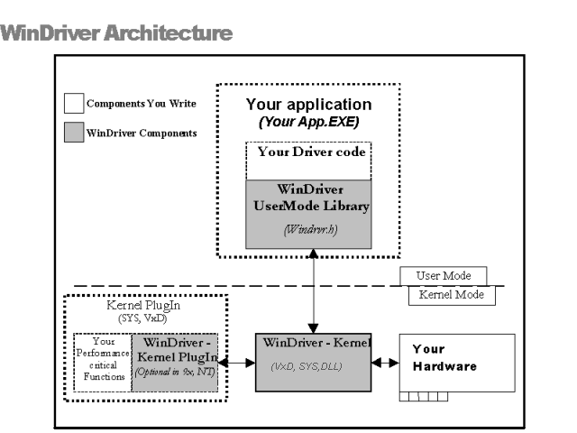
For hardware access, your application calls one of the WinDriver functions from the WinDriver User Mode library (windrvr.h). The User Mode library calls the WinDriver Kernel, which accesses the hardware for you, through the native calls of the operating system.
WinDriver's design minimizes performance hits on your code, even though it is running in the User Mode. However, some hardware drivers need performance, which cannot be achieved from the User Mode. This is where WinDriver's edge sharpens - after easily creating and debugging your code in the User Mode, you may `drop' the performance critical modules of your code (such as a hardware interrupt handler) into the WinDriver Kernel PlugIn without changing a single line of it. Now, WinDriver Kernel calls this module from the Kernel Mode, thereby achieving maximal performance. This allows you to program and debug in the User Mode, and still achieve kernel performance where needed. In Windows CE and VxWorks there is no separation between User Mode and Kernel Mode, therefore you may achieve optimal performance directly from the user mode, eliminating the need to use the Kernel PlugIn in this OS.
Yes! ¡ Evaluation versions of WinDriver for all supported operating systems and buses are available at the Jungo web site at http://www.jungo.com/dnload.html
All the evaluation versions of WinDriver are full featured. No functions are limited or crippled in any way. The following is a list of the differences between the evaluation versions and the registered ones:
From version 5.0 and onwards,WinDriver offers a GUI DriverWizard that facilitates Driver Development on Linux and Solaris. Use the GUI DriverWizard for Linux and Solaris in the same way as you use the one on Windows and then generate Linux and Solaris code.
If you are using WinDriver 4.x and below, and you do not use the Linux or Solaris X11 GUI,you may consider Windows as your initial development platform. It is recommended to start the development process on your Windows machine, using DriverWizard in the same way as described above.
If you do not have a Windows machine, you may use the sample files included with WinDriver as skeletons for your driver and change them using the WinDriver API.
For embedded operating systems, like Windows CE or VxWorks, you can use the new Remote WinDriver feature. Just run DriverWizard on a supported Host platform and you can detect and diagnose your hardware on the remote embedded target using the new Remote WinDriver option.
Note: Cross-endian network communication support is not yet provided and therefore both the host and the target machine must have the same endian scheme when using Remote WinDriver. For example, when detecting and diagnosing hardware on a Motorola PPC target architecture, you can use a Sparc machine as a compatible host since both Motorola and Sparc use the same endian scheme.
The following modules are included in your WinDriver toolkit:
NOTE:PCMCIA_SCAN.EXE is found only in the WinDriver CE version.
The CE version includes:
These are APIs that support the major PCI bridge chip-sets, for even faster code development.
Each of these directories includes the following subdirectories:
Here you will find the source code for the utilities listed above, along with other samples which show how various driver tasks are performed. Find the sample which is closest to the driver you need. Use it to jump-start your driver development process.
Yes. WinDriver is purchased as a development toolkit, and any device driver created using WinDriver may be distributed royalty free in as many copies as you wish. See the license agreement (\windriver\docs\license.txt) for more details.
The following is an overview of the common types of device driver architectures:
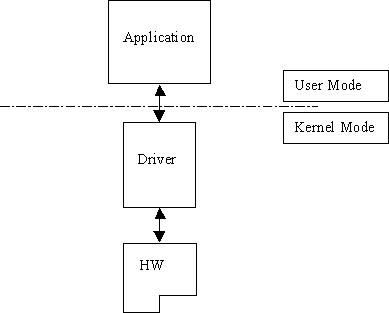
These are the device drivers that are primarily used to drive custom hardware. A monolithic driver is accessed by one or more user applications, and directly drives a hardware device. The driver communicates with the application through I / O control commands - (IOCTLs), and drives the hardware through calling the different DDK, ETK, DDI/DKI functions.
Monolithic drivers are encountered under all operating systems including all Windows platforms (95/98/ME, NT/2000, CE), all Unix platforms (Linux, VxWorks and Solaris), and others like OS/2.
We use the term Windows drivers to mean VxD drivers that run on the related family of OS's, Windows 95, Windows 98 and Windows ME. These drivers do not work on Windows NT. Windows drivers are typically monolithic in nature. They provide direct access to hardware and privileged operating system functions. These drivers are called VxD drivers. Windows drivers can be stacked or layered in any fashion. However, the driver structure itself does not impose any layering.
Besides monolithic drivers, Windows NT defines other kinds of drivers that are generally unique to Windows NT, but subsets or minor variations of which, are supported on other Windows operating systems like Windows 95/98/ME and WinCE. These are discussed below.
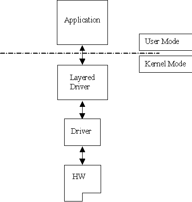
Layered drivers are device drivers that are part of a ``stack'' of device drivers, that together process an I/O request. An example of a layered driver is a driver that intercepts calls to the disk, and encrypts / decrypts all data being written / read from the disk. In this example, a driver would be hooked on to the top of the existing driver and would only do the encryption / decryption.
Layered drivers are sometimes also known as filter drivers. These are also supported on Windows 95/98/ME.
There are classes of device drivers in which much of the code has to do with the functionality of the device, and not with the device's inner workings.
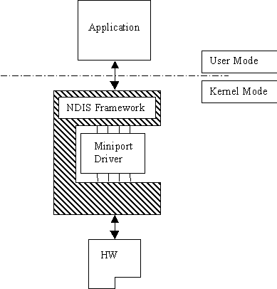
Windows NT/2000, for instance, provides several driver classes (called ``ports'') that handle the common functionality of their class. It is then up to the user to add only the functionality that has to do with the inner workings of the specific hardware.
An example of Miniport drivers is the ``NDIS'' miniport driver. The NDIS miniport framework is used to create network drivers that hook up to NT's communication stacks, and are therefore accessible by the common communication calls from within applications. The Windows NT kernel provides drivers for the different communication stacks, and other code that is common to communication cards. Due to the NDIS framework, the network card developer does not have to write all of this code, the developer must only write the code that is specific to the network card that he is developing.
In the classic Unix driver model, devices belong to three categories, character (char) devices, block devices and network devices. Drivers that implement these devices are correspondingly known as char drivers, block drivers or network drivers. Under Unix, drivers are code units that are linked into the kernel, and run in privileged kernel mode. Generally, driver code runs on behalf of the user mode application. Access to Unix drivers from user mode applications is provided via the filesystem. In other words, devices appear to the applications as special device files that can be opened.
The three classes of devices are:
Block Block devices are also accessed as files, and are
implemented by block drivers. Block devices are generally used to represent
hardware on which you can implement a file system. Typically, block devices
are accessed by multiples of a block of data at a time. Block sizes are
typically 512 bytes or 1 Kilobyte (1024 bytes). Block drivers interface
with the kernel through a similar interface as a char driver. The device
node for a block device shows differently in the filesystem listing.
Network Network interfaces are used to perform network transactions between
applications residing on a network. A network interface may work through
a hardware device or sometimes be implemented completely in software,
like the loopback interface. User applications perform network transactions
through interfaces to the kernel network subsystem (usually exposed as API
such as sockets and pipes). Network interfaces send and receive network
packets on behalf of user applications, without regard to how each individual
transaction maps to actual packets being transmitted.
Network interfaces don't easily fit into the block or char philosophy. Hence, they are not visible as device nodes in the filesystem. They are represented by system-wide unique logical names such as eth0. Clearly, network interfaces are not accessed via the open/read/write ... system calls. Instead they are accessed through network API such as sockets, pipes, RPC etc.
Linux device drivers are based on the classic Unix device driver model. In addition, Linux introduces some of its own characteristics.
Under Linux, block devices can also be accessed like a character device, but has an additional block oriented interface which is invisible to the user or application.
Traditionally, under Unix, device drivers had to be linked with the kernel, and the system had to be brought down and restarted after installing a new driver. Linux introduced the concept of a dynamically loadable driver called a module. Linux modules can be loaded or removed dynamically without requiring the system to be shut down. All Linux drivers can be written so that they are statically linked, or in modular form, which makes them dynamically loadable. This makes Linux memory usage very efficient because modules can be written to probe for their own hardware and unload themselves if they cannot find the hardware they are looking for.
Solaris device drivers are also based on the classic Unix device driver model. Like Linux, Solaris drivers may either be statically linked with the kernel, or may be dynamically loaded and removed, from the kernel.
Jungo offers two driver development products lines: WinDriver and KernelDriver. WinDriver is a tool designed for monolithic type user mode drivers. WinDriver enables you to access your hardware directly from within your Win32 application, without writing a kernel mode device driver. Using WinDriver you can either access your hardware directly from your application (in user mode) or write a DLL that you can call from many different applications.
WinDriver also provides a complete solution for high performance drivers. Using WinDriver's Kernel PlugIn, you can `drop' your user mode code into the kernel and reach full kernel mode performance.
A driver created with WinDriver runs on Windows 95, 98, ME, NT, 2000, CE, Linux, Solaris, VxWorks and OS/2. Typically, a developer without any previous driver knowledge can get a driver running in a matter of a few hours (compared to several weeks with a kernel mode driver).
There are situations that require drivers to be running in the kernel mode. Network drivers under Linux and Windows for example, almost always need to reside in the kernel. In addition under Windows NT, for layered or miniport drivers, kernel programming is necessary. To simplify this difficult task, Jungo provides ``KernelDriver'' - a tool kit for writing kernel mode drivers for Windows platforms (95/98/ME/NT/2000) and Linux. In addition, KernelDriver has special support for NT/2000 - a C++ toolkit that provides classes that encapsulate thousands of lines of kernel code, enabling you to focus on your driver's added-value functionality, instead of your OS internals.
This chapter explores the basic characteristics of the USB bus and introduces WinDriver USB features and architecture.
USB, short for Universal Serial Bus, is a new industry-standard extension to the PC architecture, for attaching peripherals to the computer. The Universal Serial Bus was originally developed in 1995 by leading PC and telecommunication industry companies, such as Intel, Compaq, Microsoft and NEC. The motivation for the development of USB, was fueled because of several considerations. Among them are the needs for an inexpensive and widespread connectivity solution for peripherals in general and for the ``Computer Telephony Integration'' in particular, the need for an easy to use and flexible method of reconfiguring the PC and a solution for adding a large number of external peripherals.
The USB interface meets the needs stated above. A single USB port can be used to connect up to 127 peripheral devices. USB also supports Plug-and-Play installation and hot swapping. USB 1.1 supports both isochronous and asynchronous data transfers and has dual-speed data transfer; 1.5Mbps (Megabit per second) for low-speed USB devices and 12Mbps for high-speed USB devices (much faster than the original serial port). Cables connecting the device to the PC can be up to five meters (16.4 feet) long. USB includes built-in power distribution for low power devices, and can provide limited power (maximum: 500mA of current) to devices attached on the bus.
Because of these benefits, USB is enjoying broad market acceptance today.
The next generation (USB2.0) supports a faster signalling rate of 480 Mb/S that is 40 times faster than USB 1.1. USB2.0 is fully forward and backward compatible with USB1.1 and uses the existing cables and connectors.
USB2.0 supports a connection for higher bandwidth, higher functionality PC peripherals. In addition, it has the capability to handle more simultaneously running peripherals.
USB2.0 will benefit many applications like Interactive Gaming, Broadband Internet Access, Desktop and Web Publishing, Internet Services and Conferencing.
USB Host: The USB host computer is where the USB host controller is installed, and where the client software / device driver runs. The USB host controller is the interface between the host and the USB peripherals. The host is responsible for detecting attachment and removals of USB devices, managing the control and data flow between the host and the devices, providing power to attached devices and more.
USB Hub: A USB device that enables connecting additional USB devices to a single USB port on the USB host. Hubs on the back plane of the hosts are called root hubs. Other hubs are external hubs.
USB Function: The USB device that is able to transmit or receive data or control information over the bus, and provides a function. Compound devices provide multiple functions on the USB bus.
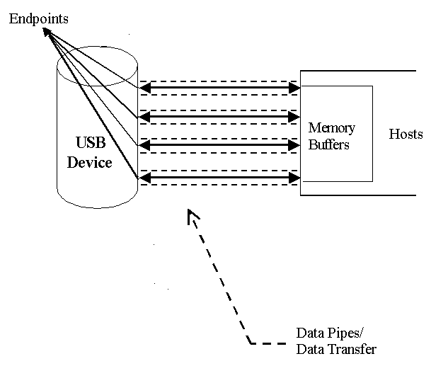
During the operation of the USB device, data flows between the client software and the device. The data is moved between memory buffers of the software on the host and the device, using pipes, which end in endpoints on the device side.
An endpoint is a uniquely identifiable entity on the USB device, which is the source or the terminus of the data that flows from or to the device. Each USB device, logical or physical, has a collection of independent endpoints. Endpoint attributes are their bus access frequency, their bandwidth requirement, their endpoint number, their error handling mechanism, the maximum packet size that the endpoint can transmit or receive, their transfer type and their direction (into the device / out of the device).
Pipes are logical components, representing associations between an endpoint on the USB device and software on the host. The data is moved to and from the device `through' a pipe. A pipe can be of two modes: stream pipe and message pipe, according to the type of data transfer used in that pipe. Pipes, sending data in interrupt, bulk or isochronous types are stream pipes, while control transfer type is supported by the message pipes. The different USB transfer types are discussed below:
The USB standard supports two kinds of data exchange between the host and the device: functional data exchange and control exchange.
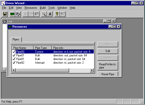
The screen shot below shows a USB device with one bi-directional control and three functional data transfer pipes/endpoints:
The USB device (function) communicates with the host by transferring data through a pipe between a memory buffer on the host and an endpoint on the device. USB provides different transfer types, that best suit the service required by the device and by the software. The transfer type of a specific endpoint is determined in the endpoint descriptor.
There are four different types of data transfer within the USB specification:
Control Transfer: Control transfer is mainly intended to support configuration, command and status operations between the software on the host and the device. Each USB device has at least one control pipe (default pipe), which provides access to the configuration, status and control information. The control pipe is a bi-directional pipe. Control transfer is bursty, non-periodic communication. Control transfer has a robust error detection, recovery and retransmission mechanism and retries are made with no involvement of the driver. Control transfer is used by low speed and high- speed devices.
Isochronous Transfer: A type usually used for time dependent information, such as multimedia streams and telephony. The transfer is periodic and continuous. The isochronous pipe is uni-directional and a certain endpoint can either transmit or receive information. For bi-directional isochronous communication there's a need to use two isochronous pipes, one in each direction. USB guarantees the isochronous transfer access to the USB bandwidth (that is it reserves the required amount of bytes of the USB frame) with bounded latency and guarantees the data transfer rate through the pipe unless there is less data transmitted. Up to 90% of the USB frame can be allocated to periodic transfers (isochronous and interrupt transfers). If, during configuration, there is no sufficient bus time available for the requester isochronous pipe, the configuration is not established. Since time is more important than correctness in these types of transfers, no retries are made in case of error in the data transfer, though the data receiver can determine the error that occurred on the bus. Isochronous transfer can be used only by high-speed devices.
Interrupt Transfer: Interrupt transfer is intended for devices that send and receive small amounts of data, in low frequency or in an asynchronous time frame. An interrupt transfer type guarantees a maximum service period and a retry of delivery to be attempted in the next period, in case of an error on the bus. The interrupt pipe, like the isochronous pipe, is uni-directional. The bus access time period (1-255ms for high-speed devices and 10-255ms for low-speed devices) is specified by the endpoint of the interrupt pipe. Although the host and the device can count only on the time period indicated by the endpoint, the system can provide a shorter period up to 1 ms.
Bulk Transfer: Bulk transfer is non-periodic, large packet, bursty communication. Bulk transfer typically supports devices that transfer large amounts of non-time sensitive data, and that can use any available bandwidth, such as printers and scanners. Bulk transfer allows access to the bus on availability basis, guarantees the data transfer but not the latency and provides error-check mechanism with retries attempts. If part of the USB bandwidth is not being used for other transfers, the system will use it for bulk transfer. Like previous stream pipes (isochronous and interrupt) the bulk pipe is also uni-directional. Bulk transfer can only be used by high-speed devices.
Before the USB function (or functions in a compound device) can be operated, the device must be configured. The host does the configuring, by acquiring the configuration information from the USB device. USB devices report their attributes by descriptors. A descriptor is the defined structure and format in which the data is transferred. A complete description of the USB descriptors can be found in Chapter 9 of the USB Specification (See http://www.usb.org for the full specification).
It is best to view the USB descriptors as a hierarchic structure of four levels:
Device Level: At the top level is the `device descriptor', that includes general information about the USB device, that is global information for all of the device configurations. The device descriptor describes, among other things, the device class (USB devices are divided into device classes, such as HID devices, hubs, locator devices etc.), subclass, protocol code, Vendor ID, Device ID and more. Each USB device has one device descriptor.
Configuration Level: A USB device has one or more configuration descriptors, which describe the number of interfaces grouped in each configuration and power attributes of the configuration (such as self-powered, remote wakeup, maximum power consumption and more). At a given time, only one configuration is loaded. An example of different configurations of the same device may be an ISDN adapter, where one configuration presents it with a single interface of 128KB/s and a second configuration with two interfaces of 64KB/s.
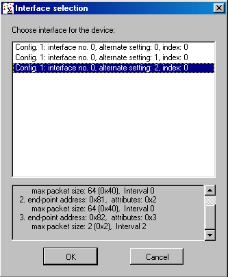
Interface Level: The interface is a related set of endpoints that present a specific functionality or feature of the device. Each interface may operate independently. The interface descriptor describes the number of the interface, number of endpoints used by this interface, and the interface specific class, subclass and protocol values when the interface operates independently. In addition, an interface may have alternate settings. The alternate settings allow the endpoints or their characteristics to be varied after the device is configured.
Endpoint Level: The lowest level is the endpoint descriptor that provides the host with information regarding the data transfer type of the endpoint and the bandwidth of each endpoint (the maximum packet size of the specific endpoint). For isochronous endpoints, this value is used to reserve the bus time required for the data transfer. Other attributes of the endpoints are their bus access frequency, their endpoint number, their error handling mechanism, and their direction.
Seems complicated? Not at all! WinDriver automates the USB configuration process. The included DriverWizard and USB diagnostics application, scan the USB bus, detect all USB devices and their different configurations, interfaces, settings and endpoints, and enables the developer to pick the desired configuration before starting driver development.
WinDriver identifies the endpoint transfer type as determined in the endpoint descriptor. The driver created with WinDriver contains all configuration information acquired at this early stage.
WinDriver USB enables developers to quickly develop high performance drivers for USB based devices, without having to learn the USB specifications or the OS internals. Using WinDriver USB, developers can create USB drivers without having to use the DDK (Microsoft Driver Development Kit), and without having to be familiar with Microsoft's WDM (Win32 Driver Module).
The driver code developed with WinDriver USB is binary compatible between Windows 2000, Windows ME and Windows 98.
The source code will be code-compatible among all other operating systems, supported
by WinDriver USB. For up to date information regarding operating systems currently
supported by WinDriver USB, please check Jungo's web site at
http://www.jungo.com
WinDriver USB encapsulates the USB specification and architecture, letting you focus on your application logic. WinDriver USB features DriverWizard, with which you can detect your hardware, configure it and test it before writing a single line of code. DriverWizard will lead you through the configuration procedure first, enable you to choose the desirable configuration, interface and alternate setting through a friendly graphical user interface. After detecting and configuring your USB device, you can then test it, listen to pipes, write and read packets and ensure that all your hardware resources function as expected. WinDriver USB is a generic tool kit, which supports all USB devices, from all vendors and with all types of configurations.
After your hardware is diagnosed, DriverWizard automatically generates your device driver source code in C or in Delphi. WinDriver USB provides user-mode APIs to your hardware, which you can call from within your application. The WinDriver USB API is specific for your USB device and includes USB unique operations such as reset-pipe and reset-device. Along with the device API, WinDriver USB creates a diagnostics application, which just needs to be compiled and run. You can use this application as your skeletal driver to jump-start your development cycle. If you are a VB programmer, you will find all WinDriver USB API supported for you also in VB, giving you everything you need to develop your driver in VB.
DriverWizard also automates the creation of a .INF file where needed. The .INF file is a text file used by the Plug-&-Play mechanisms of Windows 95/98/ME and Windows 2000 to load the driver for the newly installed hardware or to replace an existing driver. The .INF file includes all necessary information about the device(s) and the files to be installed. .INF files are required for hardware that identify themselves, such as USB and PCI. In some cases, the .INF file of your specific device is included in the .INF files that are shipped with the operating system. In other cases, you will need to create a .INF file for your device. WinDriver automates this process for you. More information on how to create your own .INF file with DriverWizard can be found in Chapter 4 that explains the DriverWizard. Installation instructions of .INF files can be found in Chapter 21 that illustrates how to distribute your driver.
Using WinDriver USB, all development is done in the user mode, using familiar development and debugging tools and your favorite compiler (such as MSDEV, Visual C/C++, Borland Delphi, Borland C++, Visual Basic).
WinDriver USB API is designed to give you optimized performance. In cases where native kernel mode performance is needed, use WinDriver USB's unique `KernelPlugIn' feature (included). This powerful feature enables you to write and debug your code in the user mode, and then simply `drop' it into the Kernel PlugIn for kernel mode execution. This unique architecture enables you to achieve maximum performance with user mode ease of use.
All other WinDriver USB features can be found in the WinDriver feature list in Chapter 2 that covers the USB features of WinDriver.
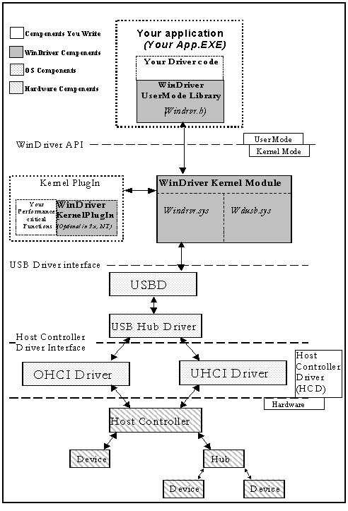
NOTE: Any occurrence of wdusb in the above figure should be read as wdpnp. As of version 5.0 the file wdusb.sys has been changed to wdpnp.sys and supports PCI, PCMCIA and USB devices.
To access your hardware, your application calls the required WinDriver USB API function from the WinDriver User Mode Library (windrvr.h). The User Mode Library calls the WinDriver Kernel Module. The WinDriver Kernel Module is comprised of windrvr.sys and wdpnp.sys. The WinDriver Kernel Module accesses your USB device resources through the native operating system calls.
There are two layers responsible to abstract the USB device to the USB device driver:
The upper one is the USB Driver layer (including the USB Driver (USBD) and USB Hub Driver) and the lower one is the host controller driver layer (HCD). The division of duties between the HCD and USBD is not defined, and is operating system dependent. Both HCD and USBD are software interfaces and components of the operating system, where the HCD layer represents a lower level of abstraction.
The HCD is the software layer that provides an abstraction of the host controller hardware while the USBD provides an abstraction of the USB device and the data transfer between the host software and the function of the USB device.
The USBD communicates with its clients (the specific device driver for example) through the USB Driver Interface ¡ USBDI. At the lower level, the USBD and USB Hub Driver implement the hardware access and data transfer by communicating with the HCD using the Host Controller Driver Interface HCDI.
The USB Hub Driver is responsible for identifying addition and removal of devices from a particular hub. Once the Hub Driver receives a signal that a device was attached or detached, it uses additional host software and the USBD to recognize and configure the device. The software implementing the configuration can include the hub driver, the device driver and other software.
WinDriver USB abstracts the configuration procedure and hardware access described above for the developer. With WinDriver USB API, developers can do all the hardware-related operations without having to master the lower levels of implementing these activities.
Almost all monolithic drivers (drivers that need to access specific USB devices), can be written with WinDriver USB. In cases where a ``standard'' driver needs to be written (e.g. NDIS driver, SCSI driver, Display driver, USB to Serial port drivers, USB layered drivers, etc.)., use KernelDriver USB (also from Jungo).
For quicker development time, select WinDriver USB over KernelDriver USB wherever possible.
This chapter takes you through the WinDriver installation process, and shows you how to check that your WinDriver is properly installed. The last section discusses the uninstallation procedure.
This procedure is explained in detail in the online documentation of the Windows CE ETK and Platform Builder.
For an up-to-date list, see the URL below:
http://www.jungo.com/db-vxworks.html#platforms
For information on BSP compatibility, please contact your nearest Wind River Systems support representative.
The WinDriver CD contains all versions of WinDriver for all the different operating systems. The CD's root directory contains the Windows 95/98/ME and NT/2000 version. This will automatically begin when you insert the CD into your CD drive. The other versions of WinDriver are located in subdirectories i.e. \ Linux, \Wince and so on.
The following steps are For Registered Users only:
Insert the WinDriver CD into your NT machine CD drive.
Exit from the auto installation and double click the ``Cd_setup.exe'' file from the \Wince directory inside the CD. This will copy all needed WinDriver files to your development platform (NT).
Copy the WinDriver CE kernel file
\windriver\redist\register\TARGET_CPU\windrvr.dll)
to the \WINDOWS subdirectory of your HPC.
Use the Windows CE Remote Registry Editor tool(ceregedt.exe)
or the Pocket Registry Editor(pregedt.exe)
on your HPC to modify your registry so that the WinDriver CE kernel is loaded
appropriately. The file
\windriver\samples\wince_install\PROJECT_WD.REG
contains the appropriate changes to be made.
Restart your HPC. The WinDriver CE kernel will be automatically loaded. You will have to do a warm RESET rather than just Suspend/Resume. You should look for a button labelled RESET on your HPC. On the HP 3xx/6xx series, this button can be found under the reserve battery cover.
Compile and run the sample programs (see Section 3.4 that describes how to check your installation) to make sure that WinDriver CE is loaded and is functioning correctly.
This environment variable is set by the WinCE ETK and may be D:\WINCE210 \RELEASE for example.
Since WinDriver installation installs the kernel module windrvr.o, WinDriver should be installed by the system administrator logged in as root, or with root privileges.
From a CD: (/usr/local> tar xvzf /mnt/cdrom/LINUX/WDxxxLN.tgz)
From a downloaded file: (/usr/local> tar xvzf /home/username /WDxxxLN.tgz)
Note: In V5.0, this directory gets created by tar, but in versions preceding 5.0, the WinDriver directory does not get created by the extraction. Therefore with older versions like 4.33, first create a directory ( say WinDriver) before proceeding with the installation. (/>mkdir /usr/local/WinDriver)
Once you activate DriverWizard you will prompted for the license string you have received when purchasing the registered version.
CAUTION: Since /dev/windrvr gives direct hardware access to user programs, it may compromise kernel stability on multi-user Linux systems. Please restrict access to DriverWizard and the device file /dev/windrvr to trusted users.
For security reasons the Windriver installation script does not automatically perform the steps of changing the permissions on /dev/windrvr and the DriverWizard executable (wdwizard).
Since WinDriver installation installs the kernel module windrvr.o, it should be installed by the system administrator logged in as root, or with root privileges.
Note: When installing WinDriver for Solaris x86 use WDxxxSL.tgz instead of WDxxxSLS.tgz.
Note: after extracting the registered kernel in step 2 you can modify the
install_windrvr (used to install the evaluation kernel) script in top dir (WinDriver)
to install the registered kernel.For this you need to perform the following change: Open
the file install_windrvr and look for the following line:
(util/wdreg redist/eval/windrvr util/windrvr.conf)
change it to: (util/wdreg redist/register/windrvr util/windrvr.conf)
CAUTION: Since /dev/windrvr gives direct hardware access to user programs, it may compromise kernel stability on multi-user Solaris systems. Please restrict to trusted users, access to DriverWizard and the device file /dev/windrvr.
For security reasons the Windriver installation script does not automatically perform the steps of changing the permissions on /dev/windrvr and the DriverWizard executable (wdwizard).
WinDriver for Solaris supports version 2.6, 7.0 and 8.0 on Intel X86 and Sparc. The same WinDriver based hardware access code will run on both platforms after recompilation.
WinDriver does not support Solaris 7 64 bit kernel. To switch from a 64 bit kernel to a 32 bit kernel follow these simple steps:
The following describes the installation of DriverBuilder for VxWorks.
DriverBuilder development
environment works with Tornado 2 for Windows only (on x86 platform).
Drivers generated using version 5.0 of DriverBuilder will run on Intel x86
BSPs (pc486, pcPentium and
pcPentiumPro), PPC 821/860 with MBX821/860 and PPC 750 (IBM PPC 604) with MCP750.
For an up-to-date list, see the URL below:
http://www.jungo.com/db-vxworks.html#platforms
To install DriverBuilder:
wddebug.out : wddebug_main
pci_diag.out : pci_diag_main
To upgrade to a new version of WinDriver, follow the steps outlined in Section 3.2.1 that illustrates the process of installing WinDriver for Windows 95/98/ME/NT/2000. You can either choose to overwrite the existing installation or install to a separate directory.
After installation, start DriverWizard and enter the new license string, if you have received one. This completes the upgrade of WinDriver.
To upgrade your source code, navigate to the RegisterWinDriver() function call in your source code, and pass the new license string as a parameter to this function. For more information on RegisterWinDriver(), please refer to the file register.txt in the directory WinDriver\redist\register.
The procedure for upgrading your installation on other operating systems is the same as the one described above. Please check the respective installation sections for installation details.
Start DriverWizard by choosing `Programs |WinDriver | DriverWizard' from the Start menu.
Registered Users
(DriverBuilder \redist\eval\intelx86\PENTIUM\windrvr.o).
       => drvrInit()

       function returned (return value = 0)

        =>
C:\DriverBuilder \samples\pci_diag\PENTIUM\pci_diag.out
from the WindShell:
=> pci_diag_main()
now you can scan the PCI bus, open cards and `talk' to them.
If for some reason you wish to uninstall either the evaluation or registered version of WinDriver, please refer to this section.
NOTE: You must be logged in as root to do the uninstallation.
Run the command rm -rf /etc/.windriver.rc to do this.
Run the command rm -rf $HOME/.windriver.rc to do this.
Run the command rm -rf /etc/.windriver.rc to do this.
Run the command rm -rf $HOME/.windriver.rc to do this.
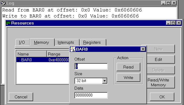
DriverWizard (included in the WinDriver toolkit) is a Windows-based diagnostics tool that lets you write to and read from the hardware, before writing a single line of code. The hardware is diagnosed through a Windows interface - memory ranges are read, registers are toggled and interrupts are checked.
Once the card is operating to your satisfaction, DriverWizard creates the skeletal driver source code, creating functions accessing all your hardware resources (where `status register' is a register you have defined on your hardware).
If you are developing a driver for a PLX based card, it is recommended to read the chapter 9 that explains WinDriver's enhanced support for specific PCI chipsets, before starting your driver development(Note: this chapter does not appear in the HLP format documentation). You can use DriverWizard to diagnose your hardware. You should use DriverWizard to generate an INF file for your card for Windows operating systems. You should avoid using DriverWizard to generate code for your PLX card because DriverWizard generates generic code and you will have to modify the code before it can be useful. We supply complete source code libraries and sample applications tailored for various PLX chipsets in the package.
DriverWizard is an excellent tool for two major phases in your HW / Driver development:
Following are the five steps in using DriverWizard:
To install the .INF file follow the instruction displayed by DriverWizard or refer to Section 21.3 that explains how to create an INF file.
Why should I create an INF file?
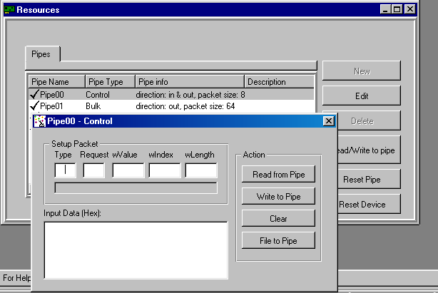
More detailed information on how to implement the control transfer and how to send Setup packets can be found under Chapter 10 that explains the WinDriver Implementation Issues
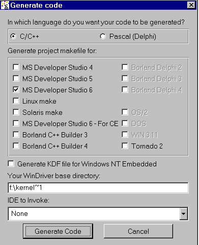
Select the WinDriver option from the `Choose type of driver' screen. Selecting the KernelDriver option will generate kernel source code designed for full kernel mode drivers. See the KernelDriver documentation or the Jungo http://www.jungo.com site url for more details (Note: this screen appears only when both WinDriver and KernelDriver are installed on your machine.)

From the following screen, choose the language in which the code will be generated , and choose your desired development environment for the various operating systems.
When two or more drivers want to share the same resource, you must define that resource as `shared'.
To define a resource as shared:
During your diagnostics, you may wish to disable a resource, so that DriverWizard will ignore it, and not create code for it.
To disable a resource
DriverWizard Logger is the blank window that opens up along with the device resources dialog when opening a new project. The logger keeps track of all your input / output in the diagnostics stage, so that the developer may analyze his device's physical performance at a later time. It is possible to save the log for future reference. When saving the project, your log is saved as well. Each log is associated with one project.
After you have finished diagnosing your device and have ensured that it runs according to your specifications, you are ready to write your driver.
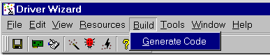
Step One ¡- Generating your code.
Choose Generate Code from the Build menu. DriverWizard will generate the source code for your driver, and place it along with the project file (xxx.wdp where xxx is your project name). The files are saved in a directory the DriverWizard creates for every development environment and operating system chosen in the `Generate Code' screen.
In the source code directory you now have a new `xxxlib.h' file which states the interface for the new functions that DriverWizard created for you, and the source of these functions `xxxlib.c', where your device specific API is implemented. In addition, you will find the sample main() function in the file `xxxdiag.c'.
The code generated by DriverWizard is composed of the following elements and files (`xxx' ¡ your project name):
xxx_lib.c ¡ Here you can find the implementation of your hardware specific API, (found in xxx_lib.h), using the regular WinDriver API.
xxx_lib.h ¡ This is the header file of the diagnostics program. Here you can find all your hardware specific API created by DriverWizard. You should include this file in your source code to use this API.
A diagnostics program, which is a console application with which you can diagnose your card. This application utilizes the special library functions, which were created for your device by DriverWizard. Use this diagnostics program as your skeletal device driver.
pci_diag_lib.c ¡ This is the source code of the diagnostics program DriverWizard creates.
Change the function main() of the program so that the functionality fits your needs.
Step 2 - Compiling the generated code
For Windows 95, 98, ME, NT, 2000 and CE (Using MSDEV)
For Windows platforms, DriverWizard generates the project files (for MSDEV 4, 5 and 6 ,C Builder and Delphi 2, 3, 4). After code generation, the chosen IDE (Integrated development environment) will be launched automatically. You can immediately compile and run the generated code.
For Linux and Solaris
DriverWizard creates a makefile for your project.
Compile the source code using the makefile generated by DriverWizard.
Use GCC to build your code.
For Other OSs or IDEs
Create a new project in your IDE (Integrated development environment).
Include the source files created by DriverWizard into your project.
Compile and run the project.
The project contains a working example of the custom functions that DriverWizard created for you. Use this example to create the functionality you want.
Remote WinDriver enables driver developers and hardware engineers to develop PCI/PCMCIA/ISA/ISA PnP/EISA/CompactPCI and USB based device drivers on any remote target including embedded systems. Remote WinDriver accesses the hardware on the remote target system from a host machine, tests it and generates a driver for it.
Remote WinDriver consists of two components:
Remote WinDriver utilizes a TCP/IP connection to communicate between the host development system and a target development system to which the hardware is plugged. On the remote target machine, WinDriver Remote Agent is installed together with the WinDriver Kernel Module, and permits access to the hardware directly from the user level in the local host development machine.
There are two ways of running this program wdremote_gui.exe:
Remote WinDriver configuration for Windows CE is different from other OSes. The following steps explain the Remote WinDriver Setup and use for Win CE.
In the eval versions, the remote agent in the CE machine will stop working after 10 mins.
NOTE: The options for the wdremote are the TCP/IP port number you wish use to communicate with the client. The default port number is 1701.
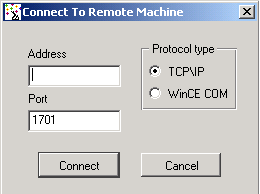
The following screen is then displayed:
Note: Use the same port number you used to start your server.
NOTE: This takes a while, so please wait for a while for the wizard to display the information of all the cards on your target machine
Just run this program as wdremote from the command line. Call this program from /etc/rc.d/rc.local/ to have it started automatically at boot time.
This chapter takes you through the WinDriver driver development cycle.
IMPORTANT NOTE: If your card's PCI bridge is either a PLX, Altera, PLDA, Galileo, QuickLogic, AMCC or V3, then WinDriver's special chip-set APIs dramatically shorten your development time. If this is the case, read the following overview, and jump straight to the chapter discussing this or refer to the electronic reference manual.
NOTE: WinDriver PLX 9050 library is fully compatible with PLX 9052. Therefore, use the files in plx/9050 directory for the PLX 9052 chip.
#include <windows.h>
#include <winioctl.h>
#include "windrvr.h"
Emulation
WinDriver is currently the only tool that enables you to test your driver code with your hardware on your NT machine ¡ under the CE emulation environment. This can dramatically shorten your development time by eliminating the need to work via a serial cable each time you want to see how your driver code operates your hardware.
If your NT host development workstation already has the target hardware plugged in, you can use the X86 HPC software emulator to test your driver. You need to generate the code as usual using DriverWizard, or from scratch as described earlier in this chapter. When compiling the code, select the target platform as X86em from the VisualC++ WCE Configuration Toolbar. You will need to link the import library windriver\redist\register\x86emu\windrvr_ce_emu.lib with your application program objects.
You may use the help files supplied to you with the WinDriver toolkit. Use these files by pressing `Start' on your task bar, and choosing `Programs | WinDriver | WinDriver Help' from there.
Debugging your hardware access application code should be approached in the manner described in the following sections
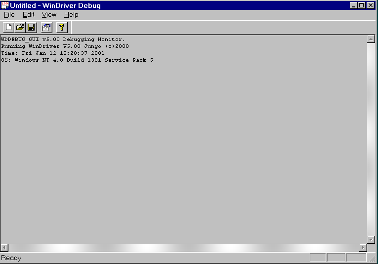
DebugMonitor is a powerful graphical and console mode tool for monitoring all activities handled by the WinDriver Kernel (windrvr.sys/ windrvr.vxd / windrvr.dll / windrvr.o / wdpnp.sys). Using this tool you can monitor how each command sent to the kernel is executed.
DebugMonitor has two modes ¡ Graphic and Console mode. The following is an explanation on how to operate DebugMonitor in both modes.
Applicable for Windows 95, 98, ME, NT, 2000. You may also use DebugMonitor to debug your CE driver code running on CE emulation on Windows NT. For Linux, Solaris, VxWorks and CE targets use the console mode DebugMonitor.
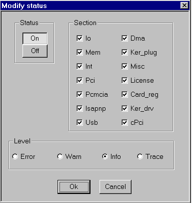
Status - Set trace on or off.
Section - Choose what part of the WinDriver API you are interested to monitor. If you are developing a PCI card and experiencing problems with your interrupt handler you should check the Int box and the PCI box.
Checking more options than necessary could amount to overflow of information making it harder for you to locate your problem. USB developers, should choose the USB box.
The Ker_drv option is for KernelDriver users, monitoring communication between their custom Kernel mode drivers (developed using KernelDriver) and the WinDriver kernel.
Level - Choose the level of messages you are interested to see for the resources defined. Error is the lowest level of trace, resulting with minimum output to the screen. Trace is the highest level of tracing displaying every operation the WinDriver Kernel performs.
Once you have defined what you want to trace and on what level just press OK to close the ``Modify status'' window, activate your program, (Step by step or in one run), and watch the monitor screen for error or any unexpected messages.
This tool is available in all operating systems supported including Linux. To use it run ``wddebug'' in the \WinDriver\util\ directory with the appropriate switches. For a list of switches available with the DebugMonitor in console mode just type ``wddebug'' and a help screen appears, describing all the different options for this command.
To see activity logged with the DebugMonitor simply type ``wddebug dump''.
On Linux and Solaris, DebugMonitor is only available in console mode. Its usage is therefore as described in Section 6.2.1.2. However, you can also start it from DriverWizard GUI using the menu selection Tools | Debug Monitor. This starts up seperate Xterm window with the command line verison of wddebug running inside it.
On Windows CE, DebugMonitor is only available in console mode. Its usage is therefore as described in Section 6.2.1.2. You first need to start a Windows CE command window (CMD.EXE) on the Windows CE target computer and then run the program WDDEBUG.EXE inside this shell.
On VxWorks, DebugMonitor is only available in console mode. Its usage is therefore as described in Section 6.2.1.2. However, because of the special syntax of the Tornado WindShell, we show a sample session with Tornado II IDE below, where we first load the debug monitor, then set the options and then run it to capture information.
-> ld < wddebug.out
Loading wddebug.out |
value = 10893848 = 0xa63a18
-> wdddebug

-> wddebug_main "on", "trace", "all"
Debug level (4) TRACE, Debug sections (0xffffffff) ALL ,
Buffer size 16384
value = 0 = 0x0
-> wddebug_main "dump"
WDDEBUG v5.00 Debugging Monitor.
Running DriverBuilder V5.00 Jungo (c) 2001 evaluation copy
Time: THU JAN 01 01:06:56 2001
OS: VxWorks
Press CTRL-BREAK to exit
Please note the following:
The WinDriver API is available from the user mode and the Kernel Plugin to WinDriver users, and from the kernel mode for KernelDriver users.
Use this Chapter as a quick reference to the WinDriver functions. The definition of the structures used in the following functions may be found in the `WinDriver Structure Reference' [8].
NOTE: If you are a registered user, you need to read the file register.txt under windriver/redist/register or kerneldriver/redist/register to understand the process of enabling your driver to work with the registered version.
Open a WinDriver device and return a handle to the device. WD_Open must be called before any other WinDriver functions can be used.
NOTE: If you are a registered user, you need to read the file register.txt under windriver/redist/register or kerneldriver/redist/register to understand the process of enabling your driver to work with the registered version.
Prototype
HANDLE WD_Open();
Return Value
INVALID_HANDLE_VALUE if device could not be opened, otherwise returns the handle.
Example
HANDLE hWD;

hWD = WD_Open();
if (hWD==INVALID_HANDLE_VALUE)
{
 printf ("Cannot open WinDriver device\n");
}
Closes the WinDriver device. This must be called when finished using the driver.
Prototype
void WD_Close(HANDLE hWD);
Parameters
hWD - handle of driver from WD_Open()
Example
WD_Close (hWD);
Returns the version of WinDriver that is currently running.
Prototype
void WD_Version( HANDLE hWD, WD_VERSION *pVer);
Parameters(WD_VERSION elements)
Example
WD_VERSION ver;

BZERO(ver);
WD_Version (hWD, &ver);
printf("%s\n", ver.cVer);
if (ver.dwVer <WD_VER)
{
 printf ("error incorrect WinDriver version \n");
}
Scan the PCI bus for cards installed.
Prototype
void WD_PciScanCards( HANDLE hWD, WD_PCI_SCAN_CARDS *pPciScan);
Parameters(WD_PCI_SCAN_CARDS elements)
Example
WD_PCI_SCAN_CARDS pciScan;
DWORD cards_found;
WD_PCI_SLOT pciSlot;

BZERO(pciScan);
pciScan.searchId.dwVendorId = 0x12bc;
pciScan.searchId.dwDeviceId = 0x1;
WD_PciScanCards (hWD, &pciScan);
if (pciScan.dwCards>0) // Found at least one card
{
 pciSlot = pciScan.cardSlot[0];
}
else
{
 printf ("No matching PCI cards found\n");
}
Get PCI card information: interrupts, I/O & memory.
Prototype
BOOL WD_PciGetCardInfo(HANDLE hWD, WD_PCI_CARD_INFO *pPciCard);
Parameters(WD_PCI_CARD_INFO elements)
Example
WD_PCI_CARD_INFO pciCardInfo;
WD_CARD Card;

BZERO(pciCardInfo);
pciCardInfo.pciSlot = pciSlot;
WD_PciGetCardInfo (hWD, &pciCardInfo);
if (pciCardInfo.Card.dwItems!=0)
{
 Card = pciCardInfo.Card;
}
else
{
 printf ("Failed fetching PCI card information\n");
}
Read / Write the PCI configuration registers.
Prototype
void WD_PciConfigDump( HANDLE hWD, WD_PCI_CONFIG_DUMP *pConfig);
Parameters(WD_PCI_CONFIG_DUMP elements)
Example
WD_PCI_CONFIG_DUMP pciConfig;
WORD aBuffer[2];

BZERO(pciConfig);
pciConfig.pciSlot.dwBus = 0;
pciConfig.pciSlot.dwSlot = 3;
pciConfig.pciSlot.dwFunction = 0;
pciConfig.pBuffer = aBuffer;
pciConfig.dwOffset = 0;
pciConfig.dwBytes = sizeof(aBuffer);
pciConfig.fIsRead = TRUE;

WD_PciConfigDump( hWD, &pciConfig);
if (pciConfig.dwResult!=PCI_ACCESS_OK)
{
 printf ("No PCI card in Bus 0 Slot 3\n");
}
else
{
 printf ("Card in Bus 0 Slot 3 has VendorID %x DeviceID %x" ,
           aBuffer[0], aBuffer[1]);
}
Scans the PCMCIA bus for PCMCIA cards installed.
Prototype
BOOL WD_PcmciaScanCards(HANDLE hWD, WD_PCMCIA_SCAN_CARDS
                       *pBuf);
Parameters(WD_PCMCIA_SCAN_CARDS elements)
Example
WD_PCMCIA_SCAN_CARDS pcmciaScan;
DWORD cards_found;
WD_PCMCIA_CARD pcmciaCard;

BZERO(pcmciaScan);
// Kingston DATAFLASH ATA Flash Card }
strcpy (pcmciaScan.searchId.cManufacturer, "Kingston Technology");
strcpy (pcmciaScan.searchId.cProductName, "DataFlash");

WD_PcmciaScanCards (hWD, &pcmciaScan);

if (pcmciaScan.dwCards > 0) // Found at least one card
{
 pcmciaCard = pcmciaScan.Card[0];
}
else
{
 printf ("No matching PCMCIA cards found");
}
Get PCMCIA card information: interrupts, I/O & memory.
Prototype
BOOL WD_PcmciaGetCardInfo(HANDLE hWD, WD_PCMCIA_CARD_INFO pPcmciaCard);
Parameters(WD_PCMCIA_CARD_INFO elements)
Example
WD_PCMCIA_CARD_INFO pcmciaCardInfo;
WD_CARD Card;

BZERO(pcmciaCardInfo);

// get this from WD_PcmciaScanCards()

pcmciaCardInfo.pcmciaSlot = pcmciaSlot;

WD_PcmciaGetCardInfo (hWD, &pcmciaCardInfo);

if (pcmciaCardInfo.Card.dwItems!=0)
{
 Card = pcmciaCardInfo.Card;
}
else
{
 printf ("Failed fetching PCMCIA card information\n");
}
Read/ Write the PCMCIA configuration registers.
Prototype
void WD_PcmciaConfigDump( HANDLE hWD, WD_PCMCIA_CONFIG_DUMP *pConfig);
Parameters(WD_PCMCIA_CONFIG_DUMP elements)
Scan the ISA bus for ISA Plug and Play cards installed.
Prototype
void WD_IsapnpScanCards( HANDLE hWD, WD_ISAPNP_SCAN_CARDS *pIsapnpScan);
Parameters(WD_ISAPNP_SCAN_CARDS elements)
Example
WD_ISAPNP_SCAN_CARDS isapnpScan;
DWORD cards_found;
WD_ISAPNP_CARD isapnpCard;

BZERO(isapnpScan);
// CTL009e - Sound Blaster ISA PnP card
strcpy (isapnpScan.searchId.cVendorId, "CTL009e");
isapnpScan.searchId.dwSerial = 0;
WD_IsapnpScanCards (hWD, &isapnpScan);
if (isapnpScan.dwCards>0) // Found at least one card
{
 isapnpCard = isapnpScan.Card[0];
}
else
{
 printf ("No matching ISA PnP cards found\n");
}
Get ISA Plug and Play card information: interrupts, I/O & memory.
Prototype
BOOL WD_IsapnpGetCardInfo(HANDLE hWD, WD_ISAPNP_CARD_INFO *pIsapnpCard);
Parameters(WD_ISAPNP_CARD_INFO elements)
Example
WD_ISAPNP_CARD_INFO isapnpCardInfo;
WD_CARD Card;

BZERO(isapnpCardInfo);
// from WD_IsapnpScanCard():
isapnpCardInfo.CardId = isapnpCard;
isapnpCardInfo.dwLogicalDevice = 0;
WD_IsapnpGetCardInfo (hWD, &isapnpCardInfo);
if (isapnpCardInfo.Card.dwItems!=0)
{
 Card = isapnpCardInfo.Card;
}
else
{
 printf ("Failed fetching ISA PnP card information\n");
}
Read / Write the ISA PnP configuration registers.
Prototype
void WD_IsapnpConfigDump( HANDLE hWD, WD_ISAPNP_CONFIG_DUMP *pConfig);
Parameters(WD_ISAPNP_CONFIG_DUMP elements)
Example
WD_ISAPNP_CONFIG_DUMP isapnpConfig;

BZERO(isapnpConfig);
// from WD_IsapnpScanCard():
isapnpConfig.CardId = isapnpCard;
isapnpConfig.dwOffset = 0;
isapnpConfig.fIsRead = TRUE;
WD_IsapnpConfigDump( hWD, &isapnpConfig);
if (isapnpConfig.dwResult!=ISAPNP_ACCESS_OK)
{
 printf ("No ISA PnP card specified slot\n");
}
else
{
 printf ("ISA PnP config in offset 0 =%x",
           isapnpConfig.bData);
}
Register card - install interrupts & map card memory. For USB devices, see WD_UsbDeviceRegister.
Must be called in order to use interrupts and perform I/O & memory transfers to card.
Prototype
void WD_CardRegister(HANDLE hWD, WD_CARD_REGISTER *pCardReg);
Parameters(WD_CARD_REGISTER elements)
FOR AN I/O RANGE ITEM
FOR A MEMORY RANGE ITEM
Card.Item[i].I.Mem.dwPhysicalAddr- first address of physical memory range.
Card.Item[i].I.Mem.dwBytes - length of range in bytes.
Card.Item[i].I.Mem.dwTransAddr - returns the base address to use for memory transfers with WD_Transfer() .
Card.Item[i].I.Mem.dwUserDirectAddr- returns the base address to use for memory transfers directly by user.
FOR AN INTERRUPT ITEM
Example
WD_CARD Card;
WD_CARD_REGISTER cardReg;

// the info for Card comes from WD_PciGetCardInfo()
// for PCI cards.
//For ISA cards the information has to be set by the user
//(IO/memory address & interrupt number).
BZERO(cardReg);
cardReg.Card = Card;
cardReg.fCheckLockOnly = FALSE;
WD_CardRegister (hWD, &cardReg);
if (cardReg.hCard==0)
 printf ("could not lock device - already in use\n");
Un-register a card, and free its resources. For USB devices see WD_UsbDeviceUnregister().
Prototype
void WD_CardUnregister(HANDLE hWD, WD_CARD_REGISTER *pCardReg);
Parameters(WD_CARD_REGISTER elements)
hCard - handle of card to un-register.
Example
WD_CardUnregister (hWD, &cardReg);
Execute a read/write instruction to I/O port or memory. For USB devices, see WD_UsbTransfer()
Prototype
void WD_Transfer(HANDLE hWD, WD_TRANSFER *pTrans);
Parameters(WD_TRANSFER elements)
FOR SINGLE TRANSFER
FOR STRING TRANSFER
Example
WD_TRANSFER Trns;
BYTE read_data;

BZERO(Trns);
Trns.cmdTrans = RP_BYTE; // Read Port BYTE
Trns.dwPort = 0x210;
WD_Transfer (hWD, &Trns);
read_data = Trns.Data.Byte;
Perform multiple I/O & memory transfers.
Prototype
void WD_MultiTransfer(HANDLE hWD, WD_TRANSFER *pTransArray, DWORD dwNumTransfers);
Parameters
Example
WD_TRANSFER Trns[4];
DWORD dwResult;
char *cData ="Message to send\n";

BZERO(Trns);
Trns[0].cmdTrans = WP_WORD;  // Write Port Word
Trns[0].dwPort = 0x1e0;
Trns[0].Data.Word = 0x1023;

Trns[1].cmdTrans = WP_WORD;
Trns[1].dwPort = 0x1e0;
Trns[1].Data.Word = 0x1022;

Trns[2].cmdTrans = WP_SBYTE;// Write Port String Byte
Trns[2].dwPort = 0x1f0;
Trns[2].dwBytes = strlen(cData);
Trns[2].fAutoinc = FALSE;
Trns[2].dwOptions = 0;
Trns[2].Data.pBuffer = cData;

Trns[3].cmdTrans = RP_DWORD;// Read Port DWord
Trns[3].dwPort = 0x1e4;

WD_MultiTransfer(hWD, Trns, 4);
dwResult = Trans[3].Data.Dword;
Note: The easiest way to handle interrupts with WinDriver is by defining the Interrupt in DriverWizard, and letting DriverWizard generate the code for you. (In Plug-n-Play cards, DriverWizard will auto-detect the interrupts for you).
Prototype
void WD_IntEnable( HANDLE hWD, WD_INTERRUPT *pInterrupt);
Parameters(WD_INTERRUPT elements)
Example
WD_INTERRUPT Intrp;
WD_CARD_REGISTER cardReg;

BZERO(cardReg);
cardReg.Card.dwItems = 1;
cardReg.Card.Item[0].item = ITEM_INTERRUPT;
cardReg.Card.Item[0].fNotSharable = TRUE;
cardReg.Card.Item[0].I.Int.dwInterrupt = 10; // IRQ 10
 // INTERRUPT_LEVEL_SENSITIVE - set to level sensitive
 // interrupts, otherwise should be 0.
 // ISA cards usually are edge sensitive, and PCI cards
 // usually are level sensitive.
cardReg.Card.Item[0].I.Int.dwOptions =
      INTERRUPT_LEVEL_SENSITIVE;
cardReg.fCheckLockOnly = FALSE;
WD_CardRegister (hWD, &cardReg);
if (cardReg.hCard==0)
    printf("could not lock device - already in use\n");
else
{
 BZERO(Intrp);
 Intrp.hInterrupt =
     cardReg.Card.Item[0].I.Int.hInterrupt;
 Intrp.Cmd = NULL;
 Intrp.dwCmds = 0;
 Intrp.dwOptions = 0;
 WD_IntEnable(hWD, &Intrp);
}
if (!Intrp.fEnableOk)
   printf("failed enabling interrupt\n");
}
Disable interrupt processing.
Prototype
void WD_IntDisable( HANDLE hWD, WD_INTERRUPT *pInterrupt);
Parameters(WD_INTERRUPT elements)
hInterrupt - handle of interrupt to disable.
Example
WD_IntDisable(hWD, &Intrp);
Wait for an interrupt.
Prototype
void WD_IntWait( HANDLE hWD, WD_INTERRUPT *pInterrupt);
Parameters(WD_INTERRUPT elements)
Example
for (;;)
{
  WD_IntWait (hWD, &Intrp);
  if (Intrp.fStopped)
     break;

ProcessInterrupt (Intrp.dwCounter);
}
Count the number of interrupts from the time WD_IntEnabled was called.
Prototype
void WD_IntCount( HANDLE hWD, WD_INTERRUPT *pInterrupt);
Parameters(WD_INTERRUPT elements)
Example
DWORD dwNumInterrupts;

WD_IntCount (hWD, &Intrp);
dwNumInterrupts = Intrp.dwCounter;
Lock a linear memory region, and return a list of the corresponding physical addresses.
Prototype
void WD_DMALock( HANDLE hWD, WD_DMA *pDma);
Parameters(WD_DMA elements)
Example 1
User buffer DMA (scatter gather locking)
WD_DMA Dma;
PVOID pBuffer = malloc (20000);

BZERO(Dma);
Dma.dwBytes = 20000;
Dma.pUserAddr = pBuffer;
Dma.dwOptions = 0;
WD_DMALock (hWD, &Dma);
// on return Dma.Page has the list of physical addresses
if (Dma.hDma==0)
 printf ("Could not lock down buffer\n");
Example 2
The following code shows kernel buffer DMA
BZERO(Dma)
Dma.dwBytes =20 * 4096; //(20 pages)
Dma.dwOptions=DMA_KERNEL_BUFFER_ALLOC;
{
WD_DMALock (hWD, &Dma);
// on return Dma.Page has the list of physical addresses
if (Dma.hDma==0)
 printf("Failed allocating kernel buffer for DMA\n");
Unlock a DMA buffer.
Prototype
void WD_DMAUnlock( HANDLE hWD, WD_DMA *pDma);
Parameters(WD_DMA elements)
hDma - handle for DMA buffer to unlock.
Example
WD_DMAUnlock (hWD, &Dma);
Delay execution for a specific amount of time. This function is used when accessing slow hardware.
Prototype
void WD_Sleep( HANDLE hWD, WD_SLEEP *pSleep);
Parameters(WD_Sleep elements)
Example
WD_SLEEP sleep;

BZERO (sleep);
sleep.dwMicroSeconds = 1000; // Sleep for 1 millisecond
sleep.dwOptions = 0;
WD_Sleep (hWD, &sleep);
Scan the USB tree for installed devices.
Prototype
void WD_UsbScanDevice(Handle hWD, WD_USB_SCAN_DEVICES *pScan);
Parameters(WD_USB_SCAN_DEVICES elements):
Example
WD_USB_SCAN_DEVICES scan;
DWORD uniqueId;

BZERO(scan);
scan.searchId.dwVendorId = 0x553;
scan.searchId.dwProductId = 0x2;
WD_UsbScanDevice(hWD, &scan);
if (scan.dwDevices > 0) // Found atleast one card
{
 uniqueId = scan.uniqueId[0];
}
else
{
 printf("No matching USB devices found\n");
}
Get information about a USB device.
Prototype
void WD_UsbGet Configuration(HANDLE hWD, WD_USB_CONFIGURATION *pConfig);
Parameters(WD_USB_CONFIGURATION elements)
Example
WD_USB_CONFIGURATION config;

BZERO(config);
config.uniqueId=2;
config.dwConfigurationIndex=0;
WD_UsbGetConfiguration(hWD, &config);
printf("found %d interfaces\n",
         config.dwInterfaceAlternatives);
Register the selected interface of the device. (This tells the hardware which interface to work with).
Must be called in order to perform data transfers on the pipes.
Prototype
void WD_UsbDeviceRegister(HANDLE hWD, WD_USB_DEVICE_REGISTER *pDevice);
Parameters (WD_USB_DEVICE_REGISTER elements)
Example
WD_USB_DEVICE_REGISTER device;

BZERO(device);
device.uniqueId = 2;
device.dwConfigurationIndex = 0;
device.dwInterfaceNum = 1;
device.dwInterfaceAlternative = 1;
WD_DeviceRegister(hWD, &device);
if(!device.{hDevice}
 printf("error - could not register device\n");
else
 printf("device has %d pipes\n", device.Device.dwPipes);
Un-register the device.
Prototype
void WD_UsbDeviceUnregister(HANDLE hWD, WD_USB_DEVICE_REGISTER
                            *pDevice);
Parameters(WD_USB_DEVICE_REGISTER elements)
hDevice - the handle of the device to un-register
Example
WD_UsbDeviceUnregister(hWD, &Device);
Perform Read / Write data transfers from / to the device using it's pipes.
Prototype
void WD_UsbTransfer(HANDLE hWD, WD_USB_TRANSFER *pTrans);
Parameters(WD_USB_TRANSFER elements)
Example
WD_USB_TRANSFER trans;

BZERO(trans);
trans.hDevice = hDevice;
trans.dwPipe = 0x81;
trans.fRead = TRUE;
trans.pBuffer = malloc(100);
trans.dwBytes = 100;
WD_UsbTransfer(hWD, &trans);
if (!fOK)
 printf("Error on Transfer\n");
else
 printf("Transferred %d bytes from %d\n",
          trans.dwBytesTransferred,trans.dwBytes);
Reset the pipe to its default state (resets the state machine of the firmware's pipe to its initial state)
Prototype
void WD_UsbResetPipe(HANDLE hWD, WD_USB_RESET_PIPE *pReset);
Parameters(WD_USB_RESET_PIPE elements)
Example
WD_USB_RESET_PIPE reset;

BZERO(reset);
reset.hDevice = hDevice;
reset.dePipe = 0x81;
WD_UsbResetPipe(hWD, &reset);
Convenience function for setting up interrupt handling. This function is implemented as a static function in the header file windrvr_int_thread.h found under windriver/include
Prototype
BOOL InterruptThreadEnable(HANDLE *phThread, HANDLE hWD, WD_INTERRUPT *pInt, HANDLER_FUNC func, PVOID pData)
Parameters
VOID interrupt_handler (PVOID pData)
{
    WD_INTERRUPT * pIntrp = (WD_INTERRUPT *) pData;
    // do your interrupt routine here
    printf ("Got interrupt %d\n", pIntrp->dwCounter);
}

....
main()
{
    WD_CARD_REGISTER cardReg;
    WD_INTERRUPT Intrp;
    HANDLE hWD, thread_handle;

    ...
    hWD = WD_Open();
    BZERO(cardReg);
    cardReg.Card.dwItems = 1;
    cardReg.Card.Item[0].item = ITEM_INTERRUPT;
    cardReg.Card.Item[0].fNotSharable = TRUE;
    cardReg.Card.Item[0].I.Int.dwInterrupt = MY_IRQ;
    cardReg.Card.Item[0].I.Int.dwOptions = 0;
    ...
    WD_CardRegister (hWD, &cardReg);
    ...
    PVOID  pData = NULL;
    BZERO(Intrp);
    Intrp.hInterrupt = cardReg.Card.Item[0].I.Int.hInterrupt;
    Intrp.Cmd = NULL;
    Intrp.dwCmds = 0;
    Intrp.dwOptions = 0;
    printf ("starting interrupt thread\n");
    pData = &Intrp;
    if (!InterruptThreadEnable(&thread_handle, hWD, &Intrp,
         interrupt_handler, pData))
      {
        printf ("failed enabling interrupt\n");
      }
    else
      {
        printf ("Press Enter to uninstall interrupt\n");
        fgets(line, sizeof(line), stdin);
        // this calls WD_IntDisable()
        InterruptThreadDisable(thread_handle);
      }
    WD_CardUnregister(hWD, &cardReg);
    ....
}
Convenience function for shutting down interrupt handling. This function is implemented as a static function in the header file windrvr_int_thread.h found under windriver/include
Prototype
VOID InterruptThreadDisable(HANDLE hThread)
Parameters
main()
{
    ....
    if (!InterruptThreadEnable(&thread_handle, hWD, &Intrp,
         interrupt_handler, pData))
      {
	printf ("failed enabling interrupt\n");
      }
    else
      {
       printf ("Press Enter to uninstall interrupt\n");
       fgets(line, sizeof(line), stdin);
       // this calls WD_IntDisable()
       InterruptThreadDisable(thread_handle);
      }
    WD_CardUnregister(hWD, &cardReg);
    ....
}
The WinDriver API is available from the user mode and the Kernel Plugin to WinDriver users, and from the kernel mode for KernelDriver users. Use this Chapter as a reference to the structures used by the WinDriver API.
This structure defines a single transfer operation to be performed by WinDriver.
Used by WD_Transfer() [7.15], WD_MultiTransfer() [7.16], WD_IntEnable() [7.17].
MEMBERS:
| TYPE | NAME | DESCRIPTION |
| DWORD | cmdTrans | Transfer command WD_TRANSFER_CMD |
| DWORD | dwPort | i/o port for transfer or user memory address |
| DWORD | dwBytes | Number of bytes for string transfer |
| DWORD | fAutoinc | transfer from one port/address or use incremental range of addresses |
| DWORD | dwOptions | must be 0 |
| Union | Data | the data for transfer |
| UCHAR | Data.Byte | Use for byte transfer |
| USHORT | Data.Word | Use for word transfer |
| DWORD | Data.Dword | Use for dword transfer |
| PVOID | Data.pBuffer | Use for string transfer |
Contains information about a DMA buffer. Used by WD_DMALock() [7.21] and WD_DMAUnlock() [7.22].
MEMBERS:
| TYPE | NAME | DESCRIPTION |
| DWORD | hDma | Handle of DMA buffer |
| PVOID | pUserAddr | Beginning of buffer |
| DWORD | dwBytes | Size of buffer |
| DWORD | dwOptions | Allocation options:
Bit masked flag - set to `0' for no option, or: DMA_KERNEL_BUFFER_ALLOC DMA_KBUF_BELOW_16M DMA_LARGE_BUFFER |
| DWORD | dwPages | Number of pages in the buffer |
| WD_DMA_ PAGE [8.3] | Page [WD_DMA_ PAGES] | Array of pages in the buffer |
MEMBERS:
| TYPE | NAME | DESCRIPTION |
| PVOID | pPhysicalAddr | physical address of page |
| DWORD | dwBytes | size of page |
Used to describe an interrupt
Used by WD_IntEnable() [7.17], WD_IntDisable() [7.18], WD_IntWait() [7.19], WD_IntCount() [7.20], InterruptThreadEnable() [7.30].
MEMBERS:
| TYPE | NAME | DESCRIPTION |
| DWORD | hInterrupt | handle of interrupt |
| DWORD | dwOptions | interrupt options:
Bit masked flag. May be `0' for no option, or: INTERRUPT_LEVEL_SENSITIVE (for level sensitive interrupts) or INTERRUPT_CMD_COPY(choose this when you need the WinDriver kernel to copy theactions of the read command it has done to acknowledge the interrupt, back to the user mode) |
| WD_TRANSFER [8.1] | *Cmd | Pointer to commands to perform on interrupt |
| DWORD | dwCmds | number of commands |
| WD_KERNEL_ PLUGIN_CALL | kpCall | kernel plugin call |
| DWORD | fEnableOk | `1' if WD_IntEnable() succeeded |
| DWORD | dwCounter | number of interrupts received |
| DWORD | dwLost | number of interrupts not yet dealt with |
| DWORD | fStopped | was interrupt disabled during wait |
Describes version of WinDriver in use. Used by WD_Version() [7.3].
MEMBERS:
| TYPE | NAME | DESCRIPTION |
| DWORD | dwVer | version |
| CHAR | cVer[100] | string of version |
Holds a handle to a registered card.
Used by WD_CardRegister() [7.13], WD_CardUnregister() [7.14].
MEMBERS:
| TYPE | NAME | DESCRIPTION |
| WD_CARD | Card | card to register |
| DWORD | fCheckLock Only | only check if card is lockable, return hCard=1 if OK |
| DWORD | hCard | handle of card |
Describes the card's resources.
MEMBERS:
| TYPE | NAME | DESCRIPTION |
| DWORD | dwItems | Number of items in card |
| WD_ITEMS [8.8] | Item [WD_CARD_ ITEMS] | Array of items[0...dwItems-1] |
Defines each item (resource) in a card.
MEMBERS:
| TYPE | NAME | DESCRIPTION |
| DWORD | item | ITEM_TYPE |
| DWORD | fNotSharable | If TRUE, item may not be shared. |
| union | I | Item specific information |
| struct | I.Mem | ITEM_MEMORY |
| DWORD | I.Mem.dw PhysicalAddr | Physical address on card |
| DWORD | I.Mem.dwBytes | Address range |
| DWORD | I.Mem.dwTrans Addr | Returns the address to pass on to transfer commands |
| DWORD | I.Mem.dwUser DirectAddr | Returns the address for direct user read/write |
| DWORD | dwCpuPhysical Addr | returns the CPU physical address of card |
| struct | I.IO | ITEM I/O |
| DWORD | I.IO.dwAddr | Beginning of I/O address |
| DWORD | I.IO.dwBytes | I/O range |
| struct | I.Int | ITEM INTERRUPT |
| DWORD | I.Int.dwInterrupt | Number of the interrupt to install |
| DWORD | I.Int.dwOptions | interrupt options:INTERRUPT_LEVEL_SENSITIVE |
| DWORD | I.Int.hInterrupt | Returns the handle of the interrupt installed |
Defines a sleep command.
Used by WD_Sleep() [7.23].
MEMBERS:
| TYPE | NAME | DESCRIPTION |
| DWORD | dwMicro Seconds | Sleep time in micro seconds - 1/1,000,000 of a second. |
| DWORD | dwOptions | should be zero |
Defines a physical location of a PCI card.
MEMBERS:
| TYPE | NAME | DESCRIPTION |
| DWORD | dwBus | PCI physical bus number of card |
| DWORD | dwSlot | PCI physical slot number of card |
| DWORD | dwFunction | PCI function on card |
Defines the identity of a PCI card.
MEMBERS:
| TYPE | NAME | DESCRIPTION |
| DWORD | dwVendorId | The PCI Vendor ID of the card. |
| DWORD | dwDeviceId | The PCI Device ID of the card. |
Receives information on cards detected on the PCI bus.
Used by WD_PciScanCards() [7.4].
MEMBERS:
| TYPE | NAME | DESCRIPTION |
| WD_PCI_ID | searchId | If searchId.dwVendorId==0, then scan all vendor IDs.
If searchId.dwDeviceId==0, then scan all device IDs. |
| DWORD | dwCards | Number of cards found |
| WD_PCI_ID [8.11] | cardId [WD_PCI_ CARDS] | VendorID & DeviceID of cards found |
| WD_PCI_SLOT [8.10] | cardSlot [WD_PCI_ CARDS] | PCI slot info of cards found |
Describes a PCI card's resources detected.
Used by WD_PciGetCardInfo() [7.5].
MEMBERS:
| TYPE | NAME | DESCRIPTION |
| WD_PCI_ SLOT [8.10] | pciSlot | PCI slot |
| WD_CARD [8.7] | Card | get card parameters for PCI slot |
Defines a read / write command to the PCI configuration registers of a PCI card.
Used by WD_PciConfigDump() [7.6].
MEMBERS:
| TYPE | NAME | DESCRIPTION |
| WD_PCI_ SLOT [8.10] | pciSlot | PCI bus,slot and function number |
| PVOID | pBuffer | buffer for read/write |
| DWORD | dwOffset | offset in PCI configuration space to read/write from |
| DWORD | dwBytes | bytes to read/write from/to buffer
Returns the number of bytes read/written |
| DWORD | fIsRead | FALSE - write PCI config
TRUE - read PCI config |
| DWORD | dwResult | 0 - PCI_ACCESS_OK - read/write ok
1 - PCI_ACCESS_ERROR - error 2 - PCI_BAD_BUS - bus does not exist (read only) 3 - PCI_BAD_SLOT - slot or function does not exist (read only) |
Identifies a specific ISA Plug and Play card on the ISA bus.
MEMBERS:
| TYPE | NAME | DESCRIPTION |
| CHAR | cVendor [8] | Vendor ID |
| DWORD | dwSerial | Serial number of card |
Information on an ISA Plug and Play card.
MEMBERS:
| TYPE | NAME | DESCRIPTION |
| WD_ISAPNP_ CARD_ID [8.15] | cardId | Vendor ID and serial number of card found |
| DWORD | dwLogicalDevices | Number of logical devices on the card |
| BYTE | bPnPVersionMajor | ISA PnP version major |
| BYTE | bPnPVersionMinor | ISA PnP version minor |
| BYTE | bVendorVersionMajor | Vendor version major |
| BYTE | bVendorVersionMinor | Vendor version minor |
| WD_ISAPNP_ ANSI | cIdent | Device identifier |
Used to receive information on cards detected on the ISA PnP bus.
Used by WD_IsapnpScanCards() [7.10].
MEMBERS:
| TYPE | NAME | DESCRIPTION |
| WD_ISAPNP_ CARD_ID [8.15] | searchId | If searchId.cVendorId[0]==0, then scan all vendor IDs.
If searchId.dwSerial==0, then scan all serial numbers. |
| DWORD | dwCards | Number of cards found |
| WD_ISAPNP_ CARD [8.16] | Card [WD_ISAPNP_ CARDS] | cards found |
Describes an ISA PnP card device's resources detected.
Used by WD_IsapnpGetCardInfo() [7.11]
MEMBERS:
| TYPE | NAME | DESCRIPTION |
| WD_ISAPNP_ CARD_ID [8.15] | cardId | Vendor ID and serial number of card for which information is required |
| DWORD | dwLogicalDevice | Number of the logical device for which information is requested |
| WD_ISAPNP_ COMP_ID | clogicalDeviceId[8] | ascii of logical device id found |
| DWORD | dwCompatibleDevices | Number of compatible devices found |
| WD_ISAPNP_ COMP_ID | CompatibleDevice [WD_ISAPNP_COMPATIBLE_ IDS] | Compatible device IDs |
| WD_ISAPNP_ ANSI | cIdent | Identity of device |
| WD_CARD [8.7] | Card | The card resource information |
Defines a read / write command to the ISA PnP configuration registers of an ISA PnP card.
Used by WD_IsapnpConfigDump() [7.12].
MEMBERS:
| TYPE | NAME | DESCRIPTION |
| WD_ISAPNP_ CARD_ID [8.15] | cardId | VendorID and serial number of card |
| DWORD | dwOffset | offset in ISA PnP configuration space to read/write from |
| DWORD | fIsRead | if 1, then read ISA PnP config
if 0, then write ISA PnP config |
| BYTE | bData | result data of byte read/write |
| DWORD | dwResult | ISAPNP_ACCESS_RESULT |
Defines a physical location of a PCMCIA card.
MEMBERS:
| TYPE | NAME | DESCRIPTION |
| BYTE | uSocket | Specifies the socket number (first socket is 0) |
| BYTE | uFunction | Specifies the function number (first function is 0) |
Defines the identity of a PCMCIA card.
MEMBERS:
| TYPE | NAME | DESCRIPTION |
| CHAR | cVersion[WD_PCMCIA_ VERSION_LEN] | The Card's PCMCIA version |
| CHAR | cManufacturer [WD_PCMCIA_MANUFA CTURER_LEN] | Manufacturer name |
| CHAR | cProductName[WD_ PCMCIA_PRODUCT NAME_LEN] | Product name |
| USHORT | cCheckSum | Card's CRC checksum value |
Receives information on cards detected on the PCMCIA bus.
Used by WD_PcmciaScanCards() [7.7] .
MEMBERS:
| TYPE | NAME | DESCRIPTION |
| WD_PCMCIA_ ID [8.21] | searchId | if strlen(searchId.cManufacturer) ==0, then scan all Manufacturers.
if strlen(searchId.cProductName) ==0, then scan all product names. |
| DWORD | dwCards | Number of cards found |
| WD_PCMCIA_ ID [8.21] | cardId[WD_ PCMCIA_ CARDS] | Manufacturer Name, Product Name, Version and CRC Info of card found |
| WD_PCMCIA_ SLOT [8.20] | cardSlot[WD_ PCMCIA_ CARDS] | PCMCIA slot/function info of cards found |
Describes a PCMCIA card's resources detected.
Used by WD_PcmciaGetCardInfo() [7.8].
MEMBERS:
| TYPE | NAME | DESCRIPTION |
| WD_PCMCIA_ SLOT [8.20] | pcmciaSlot | PCMCIA slot information |
| WD_CARD [8.7] | Card | get card parameters for PCMCIA slot |
Defines a read / write command to the PCMCIA configuration registers of a PCMCIA card.
Used by WD_PcmciaConfigDump() [7.6].
MEMBERS:
| TYPE | NAME | DESCRIPTION |
| WD_ PCMCIA_ SLOT [8.20] | pcmciaSlot | Slot descriptor of PCMCIA card |
| PVOID | pBuffer | buffer for read/write |
| DWORD | dwOffset | offset in pcmcia PnP configuration space from which to read/write |
| DWORD | dwBytes | bytes to read from or write to buffer
Returns the number of bytes read/wrote |
| DWORD | fIsRead | if 1, then read pci config
if 0, then write pci config |
| DWORD | dwResult | PCMCIA_ACCESS_RESULT |
Defines the identity of the USB device.
MEMBERS:
| TYPE | NAME | DESCRIPTION |
| DWORD | dwVendorId | Vendor ID of the USB device |
| DWORD | dwProductId | product ID of the USB device |
Information about a pipe.
MEMBERS
| TYPE | NAME | DESCRIPTION |
| DWORD | dwNumber | The number of the pipe (Pipe 0 is the default pipe) |
| DWORD | dwMaximum PacketSize | the maximum packet size of internal transfers on the pipe |
| DWORD | type | Control, Isochronous, Bulk or Interrupt |
| DWORD | direction | In=1, out=2 or in&out=3 |
| DWORD | dwInterval | Intervals of data transfer in ms (relevant to Interrupt pipes) |
Describes a configuration.
MEMBERS
| TYPE | NAME | DESCRIPTION |
| DWORD | dwNumInter faces | the configuration number |
| DWORD | dwValue | the device value |
| DWORD | dwAttributes | the device attributes |
| DWORD | Maxpower | the device MaxPower |
Describes an interface.
MEMBERS
| TYPE | NAME | DESCRIPTION |
| DWORD | dwNumber | the interface number |
| DWORD | dwAlternate Setting | the interface alternate value |
| DWORD | dwNumEnd points | the number of endpoints in the interface |
| DWORD | dwClass | the interface class |
| DWORD | dwSubClass | the interface sub class |
| DWORD | dwProtocol | the interface protocol |
| DWORD | dwIndex | the index of the interface |
Describes an endpoint.
MEMBERS
| TYPE | NAME | DESCRIPTION |
| DWORD | dwEndpoint Address | end point address |
| DWORD | dwAttributes | end point attributes |
| DWORD | dwMaxPacket Size | maximum packet size |
| DWORD | dwInterval | interval in milli-seconds |
Holds interface data.
MEMBERS
| TYPE | NAME | DESCRIPTION |
| WD_USB_INTER FACE_DESC [8.28] | Interface | the interface description |
| WD_USB_END POINT_DESC [8.29] | Endpoints[] | list of the interface endpoints |
Holds configuration data.
MEMBERS
| TYPE | NAME | DESCRIPTION |
| DWORD | uniqueId | the unique ID of the device |
| DWORD | dwConfiguration Index | the Configuration Index |
| WD_USB_CONFIG_ DESC [8.27] | configuration | the configuration description |
| DWORD | dwInterfaceAl ternatives | number of interfaces and their alternatives. |
| WD_USB_INTER FACE [8.30] | Interface[] | list of configuration interfaces |
Holds hub information (if the selected device is a hub).
MEMBERS
| TYPE | NAME | DESCRIPTION |
| DWORD | fBusPowered | is bus powered or self powered |
| DWORD | dwPorts | number of ports on this hub |
| DWORD | dwCharacter istics | hub characteristics |
| DWORD | dwPowerOn ToPowerGood | port power on till power good in ms |
| DWORD | dwHubControl Current | max current in mA |
General information about the device.
MEMBERS
| TYPE | NAME | DESCRIPTION |
| WD_USB_ID [8.25] | deviceId | the vendor ID and product ID of the device |
| DWORD | dwHubNum | the number of the hub to which the device is attached |
| DWORD | dwPortNum | the number of the port on the hub to which the device is attached |
| DWORD | fHub | is the device itself a hub? |
| DWORD | fFullSpeed | full speed or low speed device? |
| DWORD | dwConfigurations Num | how many configurations does the device have? |
| DWORD | deviceAddress | the physical address of the device |
| WD_USB_ HUB_GENERAL_ INFO [8.32] | hubInfo | contains information about the device, if the device is a Hub |
Holds device pipes information.
MEMBERS
| TYPE | NAME | DESCRIPTION |
| DWORD | dwPipes | number of pipes |
| WD_USB_ PIPE_INFO [8.26] | Pipe[] | the list of pipes information |
Define a scan command.
MEMBERS
| TYPE | NAME | DESCRIPTION |
| WD_USB_ ID [8.25] | searchId | if dwvendorId ==0, then scan all vendor IDs.
if dwProductId ==0, then scan all products. |
| DWORD | dwDevices | Number of devices found |
| DWORD | uniqueId[] | a list of the uniqueIDs to identify the devices |
| WD_USB_ DEVICE_ GENERAL_ [8.33] | deviceGeneral Info[] | list of general information about the devices found |
Defines a transfer command.
MEMBERS
| TYPE | NAME | DESCRIPTION |
| DWORD | hDevice | handle of USB device to read from or write to |
| DWORD | dwPipe | pipe number on device |
| DWORD | fRead | read or write |
| DWORD | dwOptions | can be USB_TRANSFER_HALT to halt the previous transfer on the same pipe |
| DWORD | pBuffer | pointer to buffer to read / write |
| DWORD | dwBytes | the size of the buffer |
| DWORD | dwTimeout | transfer timeout(milliseconds) 0==> no timeout |
| DWORD | dwBytes Transfered | returns the number of bytes actually read / written |
| BYTE | SetupPacket[8] | setup packet for control pipe transfer |
| DWORD | fOK | return TRUE if the transfer is successful |
Define a device registration command.
MEMBERS
| TYPE | NAME | DESCRIPTION |
| DWORD | uniqueId | the unique ID of the device |
| DWORD | dwConfiguration Index | the index of the configuration to register |
| DWORD | dwInterfaceNum | interface to register |
| Dword | dwInterfaceAl ternate | alternate number of the interface to register |
| DWORD | hDevice | handle of the device |
| WD_USB_ DEVICE_ INFO [8.34] | Device | description of the device |
| DWORD | dwOptions | should be zero |
| CHAR | cName[32] | name of card |
| CHAR | cDescription [100] | description |
Defines a reset pipe command.
MEMBERS
| TYPE | NAME | DESCRIPTION |
| DWORD | hDevice | handle of the device |
| DWORD | dwPipe | number of the pipe to reset |
This chapter is relevant to you if you are using one of the PCI chip-sets for which WinDriver offers Enhanced support. This currently includes PLX 9030, 9050, 9052, 9054, 9060, 9080, IOP 480, Galileo gt64, IOP480, Altera, V3 PBC and AMCC 5933. WinDriver supports all other PCI chip-sets via DriverWizard and the regular WinDriver API.
In addition to the regular WinDriver API, described in the earlier chapters, WinDriver also offers a custom API for specific PCI chip-sets ¡ Currently PLX, Galileo, V3, Altera, PLDA, QuickLogic and AMCC chip-sets.
The following is an overview of the development process when using WinDriver specific PCI API:
The diagnostics program is a ready-to-run sample diagnostics application for specific PCI chip-sets. The diagnostics program accesses the hardware via WinDriver's specific PCI API (xxxLIB.C). It is written as a console mode application, and not as a GUI application, to simplify the understanding of it's source code of the diagnostics program. This will help you learn how to properly use the specific API.
This application can be used as your skeletal device driver. If your driver is not a console mode application, just remove the printf() calls from the code (you may replace them with MessageBox() if you wish).
You may find that xxx_DIAG.C is both an example of using your specific API as well as a useful diagnostics utility.
The custom diagnostics program (xxx_DIAG.EXE) accesses the hardware using WinDriver. Therefore WinDriver must be installed before xxx_DIAG is run. If WinDriver is installed correctly, a message will appear on screen at boot time displaying the WinDriver version installed.
Once WinDriver is running, you may run xxx_DIAG by clicking on Start | Programs | WinDriver | Samples | Chip_name Diagnostics.
The application will first try to locate the card, with the default VendorID and DeviceID assigned by your PCI chip vendor (for example ¡ PLX 9054 - VendorID = 0x10b5, DeviceID = 0x9054). If such a card is found you will get a message ``your PCI card found'' (``PLX 9054 card found''). If you have programmed your EEPROM to load a different VendorID/DeviceID, then at the main menu you will have to choose your card (option `Locate/Choose your board' in main menu).
Displays all the cards present on the PCI bus and their resources. (IO ranges, Memory ranges, Interrupts, VendorID / DeviceID). This information may be used to choose the card you need to access.
Chooses the active card that the diagnostics application will use. You are asked to enter the VendorID/DeviceID of the card you want to access. In case there are several cards with the same VendorID/DeviceID, you will be asked to choose one of them.
This option is available only after choosing an active card. A list of the PCI configuration registers and their READ values are displayed. These are general registers, common to all PCI cards. In order to WRITE to a register, enter its number, and then the value to write to it.
This option is available only after choosing an active card. A list of your PCI registers and their READ values are displayed. In order to WRITE to a register, enter the register number, and then enter the value to write to it.
This option is available only after choosing an active card. Use this option carefully. Accessing memory ranges, accesses the local bus on your card - If you access an invalid local address, or if you have any problem with your card (such as a problem with the IRDY signal), the CPU may hang.
Both in board READ and WRITE, the address you give will also be used to set the base address register. For More detail see the electronic reference manual.
This option will appear only if the card was set to open with interrupts. Choosing this item toggles the interrupt status (Enable / Disable). When interrupts are disabled, interrupts that the card generates are not intercepted by the application. If interrupts are generated by the hardware while the interrupts are disabled by the application, the computer may `hang'.
This option provides basic read/write access to the serial configuration EEPROM. This is available only after choosing an active card. This option assumes that the configuration EEPROM has initialized the Configuration Register, Aperture zero and one space to valid local.
This option provides a way to reset the local processor from the host.
To RESET the local host processor, choose `Enter reset duration in milliseconds'. You will be asked for the time in milliseconds.
Note: Resolution of delay time is based on PC timer tick, or approximately 55 milliseconds.
Sample uses of WinDriver for all PCI chip sets are supplied with the WinDriver toolkit.
You may find the WinDriver samples under \windriver\samples, and the WinDriver for PLX/Galileo/V3/AMCC samples under \windriver\chip_vendor. Each directory contains files.txt, which describes the various samples included.
Each sample is located in its own directory. For your convenience, we have supplied an `mdp' file alongside each `.c' file, so that users of Microsoft's Developers Studio may double-click the mdp file and have the whole environment ready for compilation. (Users of other win32 compilers need to include the *.c files in their stand-alone console project, and include the xxx_lib.c in their project)
You may use the source of the diagnostic program described earlier to learn your PCI's specific API usage.
Use this section as a `quick reference' to WinDriver's specific PCI API functions. A more detailed reference (per chip) may be found in the WinDriver's Help files.
Advanced users may find more functionality in WinDriver's API.
All the functions outlined in Chapter 7 that details the WinDriver function reference are implemented in the respective \WinDriver\chip_vendor\chip_name\lib\xxx_lib.c file.
For more detailed information on specific PCI chip set APIs see the electronic reference manual.
The definition of the structures used in the following functions are found in the Electronic Reference Manual
Returns the number of cards on the PCI bus that have the given VendorID and DeviceID.
This value can then be used when calling xxx_Open, to select which board to open. Normally, only one board is in the bus and this function will return 1.
PROTOTYPE AND PARAMETERS
See electronic reference manual for your PCI chip specific details.
RETURN VALUE
Returns the number of matching PCI cards found.
EXAMPLE
nCards = P9054_CountCards( 0x10b5, 0x9054 );
Used to open a handle to your card. If several cards with identical PCI chips are installed, the specific card to open may be specified by using `xxx_CountCards' before using `xxx_Open', and then calling `open' with a specific card number.
If Open is successful, the function returns TRUE, and a handle to the card.
PROTOTYPE AND PARAMETERS
See electronic reference manual for your PCI chip specific details.
RETURN VALUE
TRUE if OK.
EXAMPLE
if (!P9054_Open( &hPlx, 0x10b5, 0x9054, 0, P9054_OPEN_USE_INT ))

{

  printf("Error opening device\n");

}
Closes WinDriver device. Must be called after finished using the driver.
PROTOTYPE AND PARAMETERS - See electronic reference manual for your PCI chip specific details.
RETURN VALUE
None
EXAMPLE
P9054_Close(hPLX);
Checks if the specified address space is enabled. The enabled address spaces are determined by the EEPROM, which at boot time sets the memory ranges requests.
Use this function after calling xxx_Open() to make sure that the address space(s) that your driver is going to use are enabled.
PROTOTYPE AND PARAMETERS
See electronic reference manual for your PCI chip specific details.
RETURN VALUE
TRUE if address space is enabled
EXAMPLE
if ( !P9054_IsAddrSpaceActive(hPlx, P9054_ADDR_SPACE2) )

{

  printf ("Address space2 is not active!\n");

}
Returns your PCI chip-set silicon revision.
PROTOTYPE AND PARAMETERS
See electronic reference manual for your PCI chip specific details.
RETURN VALUE
Returns the silicon revision.
Reads data from a specified register on the board.
PROTOTYPE AND PARAMETERS - See electronic reference manual for your PCI chip specific details.
RETURN VALUE
Data read from register (for P9054_ReadReg() only).
Writes data to a specified register on the board.
PROTOTYPE AND PARAMETERS - See electronic reference manual for your PCI chip specific details.
RETURN VALUE
None
Reads a byte from address space on board.
PROTOTYPE AND PARAMETERS
See electronic reference manual for your PCI chip specific details.
RETURN VALUE
Data read from board.
Reads a word from address space on board.
PROTOTYPE AND PARAMETERS
See electronic reference manual for your PCI chip specific details.
RETURN VALUE
Data read from board.
Reads a dword from address space on board.
PROTOTYPE AND PARAMETERS
See electronic reference manual for your PCI chip specific details.
RETURN VALUE
Data read from board.
Writes a byte from address space on board.
PROTOTYPE AND PARAMETERS
See electronic reference manual for your PCI chip specific details.
RETURN VALUE
None
Writes a word from address space on board.
PROTOTYPE AND PARAMETERS
See electronic reference manual for your PCI chip specific details.
RETURN VALUE
None
Writes a dword from address space on board.
PROTOTYPE AND PARAMETERS
See electronic reference manual for your PCI chip specific details.
RETURN VALUE
None
Reads a block from address space on board.
PROTOTYPE AND PARAMETERS
See electronic reference manual for your PCI chip specific details.
RETURN VALUE
Data read from the board
Writes a block from address space on board.
PROTOTYPE AND PARAMETERS
See electronic reference manual for your PCI chip specific details.
RETURN VALUE
None
Reads a byte from memory on board.
PROTOTYPE AND PARAMETERS
See electronic reference manual for your PCI chip specific details.
RETURN VALUE
Data read from board.
Reads a word from memory on board.
PROTOTYPE AND PARAMETERS
See electronic reference manual for your PCI chip specific details.
RETURN VALUE
Data read from board.
Reads a dword from memory on board.
PROTOTYPE AND PARAMETERS
See electronic reference manual for your PCI chip specific details.
RETURN VALUE
Data read from board.
Writes a byte to memory on board.
PROTOTYPE AND PARAMETERS
See electronic reference manual for your PCI chip specific details.
RETURN VALUE
None
Writes a word to memory on board.
PROTOTYPE AND PARAMETERS
See electronic reference manual for your PCI chip specific details.
RETURN VALUE
None.
Writes a dword to memory on board.
PROTOTYPE AND PARAMETERS
See electronic reference manual for your PCI chip specific details.
RETURN VALUE
None.
Reads a block of memory from the board.
PROTOTYPE AND PARAMETERS
See electronic reference manual for your PCI chip specific details.
RETURN VALUE
Data read from the board
Writes a block of memory to the board.
PROTOTYPE AND PARAMETERS
See electronic reference manual for your PCI chip specific details.
RETURN VALUE
None
Checks whether interrupts are enabled or not.
PROTOTYPE AND PARAMETERS
See electronic reference manual for your PCI chip specific details.
RETURN VALUE
TRUE if interrupts are already enabled (e.g. if P9054_IntEnable() was called).
Enable interrupt processing.
IMPORTANT NOTE: All PCI chip-sets use level sensitive interrupts. Hence, you must edit the implementation of this function (found in your
\WinDriver\chip_vendor\chip_name \lib\xxx_lib.c) to fit your specific hardware.
The comments in this function indicate the places where changes must be inserted. PROTOTYPE AND PARAMETERS
See the electronic reference manual for the PCI chip specific details.
RETURN VALUE
TRUE if successful.
Disable interrupt processing.
PROTOTYPE AND PARAMETERS
See electronic reference manual for your PCI chip specific details.
RETURN VALUE
None
Initializes the WD_DMA structure (see windrvr.h) and allocates a contiguous buffer
WD_DMA stucture
typedef struct {
  DWORD hDma;      // handle of dma buffer
  PVOID pUserAddr; // beginning of buffer
  DWORD dwBytes;   // size of buffer
  DWORD dwOptions; // allocation options:

                   // DMA_KERNEL_BUFFER_ALLOC,
                   // DMA_KBUF_BELOW_16M,
                   // DMA_LARGE_BUFFER

  DWORD dwPages;   // number of pages in buffer

  WD_DMA_PAGE Page[WD_DMA_PAGES];

} WD_DMA, WD_DMA_V30;
The definition of the structure WD_DMA_PAGE is as follows:
typedef struct {
  PVOID pPhysicalAddr; // physical address of page
  DWORD dwBytes;       // size of page
} WD_DMA_PAGE, WD_DMA_PAGE_V30;
PROTOTYPE AND PARAMETERS
See electronic reference manual for your PCI chip specific details.
RETURN VALUE
Returns TRUE if DMA buffer allocation succeeds
Frees the DMA handle, and frees the allocated contiguous buffer.
PROTOTYPE AND PARAMETERS
See electronic reference manual for your PCI chip specific details.
RETURN VALUE
None
Start DMA to or from the card.
PROTOTYPE AND PARAMETERS
See electronic reference manual for your PCI chip specific details.
RETURN VALUE
Returns TRUE if DMA transfer succeeds.
Used to test if DMA is done. (Use when V3PBC_DMAStart is called with fBlocking == FALSE)
PROTOTYPE AND PARAMETERS
See electronic reference manual for your PCI chip specific details.
RETURN VALUE
Returns TRUE if DMA transfer is completed.
Sends a reset signal to the card, for a period of `wDelay' milliseconds.
PROTOTYPE AND PARAMETERS
See electronic reference manual for your PCI chip specific details.
RETURN VALUE
None
Reads data from the EEPROM. - Syntax and functionality may vary between different chip-sets. See the electronic reference manuals for your chip-set's exact syntax and usage.
PROTOTYPE AND PARAMETERS
See the electronic reference manual for your PCI chip specific details
RETURN VALUE
Returns the data read.
Writes data to the EEPROM. - Syntax and functionality may vary between different chip-sets. See the electronic reference manuals for your chip-set's exact syntax and usage.
PROTOTYPE AND PARAMETERS
See the electronic reference manual for your PCI chip specific details
RETURN VALUE
Returns TRUE if EEPROM write succeeds.
Read data from the PCI configuration registers.
PROTOTYPE AND PARAMETERS
See electronic reference manual for your PCI chip specific details.
RETURN VALUE
Data read from configuration register
Write to the PCI configuration registers.
PROTOTYPE AND PARAMETERS
See electronic reference manual for your PCI chip specific details.
RETURN VALUE
None
Structure Reference for WinDriver's specific PCI APIs
Structure reference for the PLX, Galileo, Altera, V3, and AMCC specific APIs can be found in the electronic version of the manual.
This chapter contains instructions for performing operations that DriverWizard cannot automate. If you are using a PCI chip set from PLX, Galileo, Altera, AMCC, or V3 ¡ you do not have to read this chapter.
WinDriver includes custom APIs built especially for these PCI chip-set vendors. These APIs save you the need to learn both the PCI internals and the chip-set's data sheets. Using these specific APIs ¡ a DMA function is as simple as calling a function (i.e. P9054_DMAOpen(), P9054_DMAStart() and so on... ).
If you are not using a PCI chip which has enhanced support WinDriver (currently - PLX, Galileo, Altera, V3 or AMCC) ¡ these few pages will guide you through the steps of performing DMA via WinDriver's API.
There are basically two methods to perform DMA - Contiguous Buffer DMA and Scatter/Gather DMA. Scatter/Gather DMA is much more efficient than contiguous DMA. This feature allows the PCI device to copy memory blocks from different addresses. This means that the transfer can be done directly to/from the user's buffer - that is contiguous in Virtual memory, but fragmented in the Physical memory. If your PCI device does not support Scatter/Gather, you will need to allocate a physically contiguous memory block, perform the DMA transfer to there, and then copy the data to your own buffer.
The programming of DMA is specific for different PCI devices. Normally, you need to program your PCI device with the Local address (on your PCI device), the Host address (the physical memory address on your PC), the transfer count (size of block to transfer), and then set the register that initiates the transfer.
Following is an outline of a DMA transfer routine for PCI devices that support Scatter/Gather DMA. More detailed examples can be found at:
Note for Linux developers: Due to Linux's own limitations WinDriver does not yet support Scatter Gather DMA on this OS. This feature will be added to the Linux version of WinDriver as soon as the Linux kernel includes support for Scatter Gather DMA operations.
Sample DMA implementation:
BOOL DMA_routine(void *startAddress, DWORD transferCount,
 BOOL fDirection)

{

  WD_DMA dma;

  int i;

  BZERO (dma);

  dma.pUserAddr = startAddress;

  dma.dwBytes = transferCount;

  dma.dwOptions = 0;

  // lock region in memory
  WD_DMALock(hWD,&dma);
  if (dma.hDma==0)
    return FALSE;
  for(i=0;i!=dma.dwPages;i++)
  {
    // Program the registers for each page of the transfer
    My_DMA_Program_Page(dma.Page[i].pPhysicalAddr,
     dma.Page[i].dwBytes, fDir);
  }
  // write to the register that initiates the DMA transfer
  My_DMA_Initiate();
    // read register that tells when the DMA is done
  while(!My_DMA_Done());
  WD_DMAUnlock(hWD,&dma);
  return TRUE;

}
You should implement:
The WD_DMA structure holds a list of 256 pages. The x86 CPU uses 4K page size, so 256 pages can hold 256*4K = 1MB. Since the first and last page might not start (or end) on a 4096 byte boundary, 256 pages can hold 1MB - 8K.
If you need to lock down a buffer larger than 1MB, that needs more than 256 pages, you will need the DMA_LARGE_BUFFER option.
BOOL DMA_Large_routine(void *startAddress, DWORD transferCount,
    BOOL fDirection)
{
  DWORD dwPagesNeeded = transferCount / 4096 + 2;
  WD_DMA *dma=calloc
   (sizeof(WD_DMA)+sizeof(WD_DMA_PAGE)*dwPagesNeeded,1);
  dma->pUserAddr = startAddress;
  dma->dwBytes = transferCount;
  dma->dwOptions = DMA_LARGE_BUFFER;
  dma->dwPages = dwPagesNeeded;
  // lock region in memory
  WD_DMALock(hWD,&dma);
  // the rest is the same as in the DMA_routine()
  // free the WD_DMA structure allocated
  free (dma);
}
More detailed examples can be found at:
A read sequence (from the card to the mother-board's memory):
{
  WD_DMA dma;
  BZERO (dma);
  // allocate the DMA buffer (100000 bytes)
  dma.pUserAddr = NULL;
  dma.dwBytes = 10000;
  dma.dwOptions = DMA_KERNEL_BUFFER_ALLOC;
  WD_DMALock(hWD, &dma);
  if (dma.hDma==0)
    return FALSE;
  // transfer data from the card to the buffer
  My_Program_DMA_Transfer(dma.Page[0].pPhysicalAddr,
  // Wait for transfer to end
  while(!My_Dma_Done());
  // now the data is the buffer, and can be used
  UseDataReadFromCard(dma.pUserAddr);
  // release the buffer
  WD_DMAUnlock(hWD,&dma);
}
A Write Sequence (from the mother-board's memory to the card):
{

  WD_DMA dma;

  BZERO (dma);

  //allocate the DMA buffer (100000 bytes)

  dma.pUserAddr = NULL;

  dma.dwBytes = 10000;

  dma.dwOptions = DMA_KERNEL_BUFFER_ALLOC;

  WD_DMALock(hWD, &dma);

  if (dma.hDma==0)

    return FALSE;

  // prepare data into buffer

  PrepareDataInBuffer(dma.pUserAddr);

  // transfer data from the buffer to the card

  My_Program_DMA_Transfer(dma.Page[0].pPhysicalAddr,
   LocalAddr);

  // Wait for transfer to end

  while(!My_Dma_Done());

  // release the buffer

  WD_DMAUnlock(hWD,&dma);

}
Interrupts can easily be handled via DriverWizard. It is recommended that you use DriverWizard to generate the interrupt code for you, by defining (or auto-detecting) your hardware's interrupts, and generating code. Use this section to understand the code DriverWizard generates for you or to write your own Interrupt handler.
The WD_IntWait() function, puts the thread to sleep until an interrupt occurs. There is no CPU consumption while waiting for an interrupt. Once an interrupt occurs, it is first handled by the WinDriver kernel, then the WD_IntWait() wakes up the interrupt handler thread and returns.
Since your interrupt thread runs in user-mode, you may call any Windows API function, including File handling and GDI functions.
Simple interrupt handler routine, for edge-triggered interrupts (normally ISA/EISA cards):
// interrupt structure

WD_INTERRUPT Intrp;

DWORD WINAPI wait_interrupt (PVOID pData)

{

  printf ("Waiting for interrupt");
  for (;;)

  {

    WD_IntWait (hWD, &Intrp);
    if (Intrp.fStopped)

      break; // WD_IntDisable called by parent
  // call your interrupt routine here
      printf ("Got interrupt %d\n", Intrp.dwCounter);

  }
  return 0;
}

void Install_interrupt()
{
  BZERO(Intrp);
  // put interrupt handle returned by WD_CardRegister
  Intrp.hInterrupt = cardReg.Card.Item[0].I.Int.hInterrupt;
  // no kernel transfer commands to do upon interrupt
  Intrp.Cmd = NULL;
  Intrp.dwCmds = 0;
  // no special interrupt options
  Intrp.dwOptions = 0;
  WD_IntEnable(hWD, &Intrp);
  if (!Intrp.fEnableOk)
  {
    printf ("Failed enabling interrupt\n");
    return;
  }

  printf ("starting interrupt thread\n");

  thread_handle = CreateThread (0, 0x1000,
    wait_interrupt, NULL, 0, &thread_id);

  // call your driver code here

  WD_IntDisable (hWD, &Intrp);
  WaitForSingleObject(thread_handle, INFINITE);

}
From Version 4.3 onwards, a new header file windrvr_int_thread.h simplifies the code you need to write to handle interrupts. In this header file - found under windriver/include, we provide the convienence functions InterruptThreadEnable [7.30] and InterruptThreadDisable [7.31]. These functions are implemented as static functions in the header file windrvr_int_thread.h. Please study the code in the header file to understand how this operates. We may rewrite the code from Section 10.2.1 as follows. This code was extracted from the sample program int_io.c which can be found under windriver/samples/int_io. Please refer to this file for the full listing.
// interrupt handler routine. you can use pData to pass
// information from InterruptThreadEnable()
VOID interrupt_handler (PVOID pData)
{
    WD_INTERRUPT * pIntrp = (WD_INTERRUPT *) pData;
    // do your interrupt routine here
    printf ("Got interrupt %d\n", pIntrp->dwCounter);
}

...

int main()
{
    HANDLE hWD;
    WD_CARD_REGISTER cardReg;
    // interrupt structure
    WD_INTERRUPT Intrp;
    HANDLE thread_handle;

    ...
    hWD = WD_Open();
    BZERO(cardReg);
    cardReg.Card.dwItems = 1;
    cardReg.Card.Item[0].item = ITEM_INTERRUPT;
    cardReg.Card.Item[0].fNotSharable = TRUE;
    cardReg.Card.Item[0].I.Int.dwInterrupt = MY_IRQ;
    cardReg.Card.Item[0].I.Int.dwOptions = 0;
    ...
    WD_CardRegister (hWD, &cardReg);
    ...
    PVOID  pData = NULL;
    BZERO(Intrp);
    Intrp.hInterrupt = cardReg.Card.Item[0].I.Int.hInterrupt;
    Intrp.Cmd = NULL;
    Intrp.dwCmds = 0;
    Intrp.dwOptions = 0;
    printf ("starting interrupt thread\n");
    // this calls WD_IntEnable() and creates an interrupt
    // handler thread which calls the function
    // interrupt_handler with the pointer pData as a parameter

    pData = &Intrp;
    ...
    if (!InterruptThreadEnable(&thread_handle, hWD, &Intrp,
         interrupt_handler, pData))
      {
         printf ("failed enabling interrupt\n");
      }
    else
      {
        // call your driver code here
        printf ("Press Enter to uninstall interrupt\n");
        fgets(line, sizeof(line), stdin);

        // this calls WD_IntDisable()
        InterruptThreadDisable(thread_handle);
      }
    WD_CardUnregister(hWD, &cardReg);
    ....
}
In the above code, the function interrupt_handler serves as our ``interrupt handler'', getting invoked once for every interrupt that occurs. In the simplified code for setting up the interrupt handling, we call InterruptThreadEnable[7.30] spawn a thread that calls the function interrupt_handler - a pointer to this function is passed as the fourth parameter to InterruptThreadEnable - each time an interrupt occurs, passing into this function, the data pData specified by the fifth parameter.
Generally, ISA/EISA interrupts are edge triggered, as opposed to PCI interrupts that are level sensitive. This difference has many implications on writing the interrupt handler routine.
Edge triggered interrupts are generated once, when the physical interrupt signal goes from low to high. Therefore, exactly one interrupt is generated. This makes the Windows OS to call the WinDriver kernel interrupt handler, that released the thread waiting on the WD_IntWait() function. There is no special action that needs to take place in order to acknowledge this interrupt.
Level sensitive interrupts are generated as long as the physical interrupt signal is high. If the interrupt signal is not lowered by the end of the interrupt handling by the kernel, the Windows OS will call the WinDriver kernel interrupt handler again - This will cause the PC to hang!
To prevent this situation from happening, the interrupt must be acknowledged by the WinDriver kernel interrupt handler. Explanation on acknowledging level-sensitive interrupts can be found under Section 19.6 that explains how to deal with the problem of the computer hanging on interrupt.
Transfer commands at kernel-level (acknowledging the interrupt)
Usually, interrupt handlers for PCI cards (level sensitive interrupt handlers) need to perform transfer commands at the kernel to lower the interrupt level (acknowledge the interrupt).
To pass transfer commands to be performed in the WinDriver kernel interrupt
handler, before WD_IntWait() returns, you must prepare an array of
commands
(WD_Transfer structure), and pass it to the WD_IntEnable()
function.
WD_TRANSFER trans[2];
BZERO(trans);
trans[0].cmdTrans = RP_DWORD; // Read Port Dword
// address of IO port to write to
trans[0].dwPort = dwAddr;
trans[1].cmdTrans = WP_DWORD; // Write Port Dword
// address of IO port to write to
trans[1].dwPort = dwAddr;
// the data to write to the IO port
trans[1].Data.Dword = 0;
Intrp.dwCmds = 2;
Intrp.Cmd = trans;
Intrp.dwOptions =
      INTERRUPT_LEVEL_SENSITIVE | INTERRUPT_COPY_CMD;
WD_IntEnable(hWD, &Intrp);
This sample performs a DWORD read command from the IO address dwAddr, then it writes to the same IO port a value of `0'.
The INTERRUPT_COPY_CMD option is used to retrieve the value read by the first transfer command, before the write command is issued. This is useful when you need to read the value of a register, and then write to it to lower the interrupt level. If you try to read this register after WD_IntWait() returns, it will already be `0' because the write transfer command was issued at kernel level.
DWORD WINAPI wait_interrupt (PVOID pData)
{
   printf ("Waiting for interrupt");
   for (;;)
   {
     WD_TRANSFER trans[2];
     Intrp.dwCmds = 2;
     Intrp.Cmd = trans;
     WD_IntWait (hWD, &Intrp);
     if (Intrp.fStopped)

        break; // WD_IntDisable called by parent
               // call your interrupt routine here

        printf (
                "Got interrupt %d. Value of register read %x\n",
               Intrp.dwCounter, trans[0].Data.Dword);
}
return 0;
}
If you study the implementation of the interrupt handling in windrvr_int_thread.h, you see that code similar to the above is used there.
Windows CE uses a logical interrupt scheme rather than the physical interrupt number. It maintains an internal kernel table that maps the physical IRQ number to the logical IRQ number. Device drivers are generally expected to get the logical interrupt number after having ascertained the physical interrupt.
This is handled internally by WinDriver so programmers using WinDriver need not worry about this issue. However, the X86 CEPC builds provided with the ETK do not provide interrupt mappings for certain reserved interrupts including the following:
An attempt to initialize and use any of these interrupts will fail. In case you wish to use any of these interrupts - (e.g.: you do not want to use the PPSH and you want to reclaim the parallel port for some other purpose) - you should modify the file CFWPC.C that is found in the directory %_TARGETPLATROOT%\KERNEL\HAL to include code as shown below that sets up a value for the interrupt 7 in the interrupt mapping table.
SETUP_INTERRUPT_MAP(SYSINTR_FIRMWARE+7,7);
Supposing you have a PCI card in your X86 CEPC and the BIOS assigned IRQ9 to it. Since WinCE does not map this interrupt by default, you will not be able to receive interrupts from this card. In this case, you will need to insert a similar entry for IRQ 9.
SETUP_INTERRUPT_MAP(SYSINTR_FIRMWARE+9,9);
You will then need to rebuild the Windows CE image NK.BIN and download the new executable onto your target platform.
For non-X86 machines like the hand-held PCs from HP and Sharp, the developer should use the logical interrupt ID which can be in the platform specific header file NKINTR.H
A complete discussion of this procedure is outside the scope of this manual. Please refer to the ETK or Platform Builder documentation for more details.
Windows CE handles PCMCIA interrupts differently than PCI and ISA/EISA interrupts.
WinDriver handles the setting up of the PCMCIA interrupt internally by calling
the Card Services API so this process is transparent to the developer.
The WD_PcmciaGetCardInfo() function automatically sets up the interrupt items
and registers the interrupt.
The USB standard supports two kinds of data exchange between the host and the device: functional data exchange and control exchange.
The control transfer consists of a setup stage (in which a setup packet is sent from the host to the device), an optional data stage and a status stage.
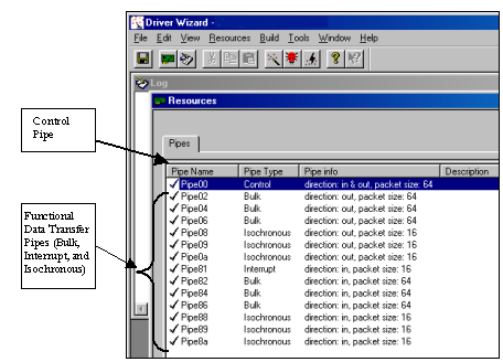
The control transaction always begins with a setup stage. Then, it is followed by zero or more control data transactions (data stage) that carry the specific information for the requested operation, and finally, a Status transaction completes the control transfer by returning the status to the host.
During the setup stage, a SETUP Packet is used to transmit information to the control endpoint of the device. The Setup Packet consists of eight bytes, and its format is specified in the USB specification.
A control transfer can be a read transaction or a write transaction. In a read transaction, the Setup Packet indicates the characteristics and amount of data to be read from the device. In a write transaction, the Setup Packet contains the command sent (written) to the device and the number of control Data bytes, associated with this transaction, that are sent to the device in the data stage.
The following figure shows the sequence of read and write transactions (the figure is taken from the USB specification). `In' means the data flows from the device to the host. `Out' means the data flows from the host to the device.
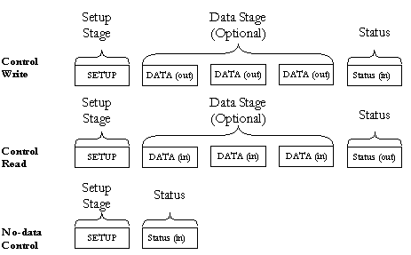
The Setup Packets (combined with the control data stage and the status stage) are used to configure and send commands to the device. Chapter 9 of the USB specification defines standard device requests. USB requests such as these are sent from the host to the device, using Setup Packets. The USB device is required to respond properly to these requests. In addition, each vendor may define device-specific Setup Packets, to perform device specific operations. The standard Setup Packets (standard USB device requests) are detailed below. The vendor's device-specific Setup Packets are detailed in the vendor's specific data book for each USB device.
The table below shows the format of the USB setup packet. (For further information please refer to the USB specification at http://www.usb.org.)
| Byte | Field | Description |
| 0 | bmRequest Type | Bit 7: Request direction (0=Host to device - out, 1=Device to host - in)
Bits 5..6:Request type (0=standard, 1=class, 2=vendor, 3=reserved) Bits 0..4:Recipient (0=device, 1=interface, 2=endpoint,3=other) |
| 1 | bRequest | The actual request (see next table) |
| 2 | wValueL | A word-size value that varies according to the request (for example in the CLEAR_FEATURE request, the value is used to select the feature, in the GET_DESCRIPTOR request, the value indicates the descriptor type, in the SET_ADDRESS request, the value contains the device address) |
| 3 | wValueH | The upper byte of the Value word. |
| 4 | wIndexL | A word size value that varies according to the request. The index is generally used to specify an endpoint or an interface. |
| 5 | wIndexH | The upper byte of the Index word. |
| 6 | wLengthL | Word size value, indicates the number of bytes to be transferred if there is a data stage. |
| 7 | wLengthH | The upper byte of the Length word. |
| bRequest | Value |
| GET_STATUS | 0 |
| CLEAR_FEATURE | 1 |
| Reserved for future use | 2 |
| SET_FEATURE | 3 |
| Reserved for future use | 4 |
| SET_ADDRESS | 5 |
| GET_DESCRIPTOR | 6 |
| SET_DESCRIPTOR | 7 |
| GET_CONFIGURATION | 8 |
| SET_CONFIGURATION | 9 |
| GET_INTERFACE | 10 |
| SET_INTERFACE | 11 |
| SYNCH_FRAME | 12 |
This is an example of a standard USB device request to illustrate the Setup Packet format and its different fields. The Setup packet is in Hex format.
The following Setup Packet is a `Control Read' transaction that retrieves the `Device descriptor' from the USB device. The `Device descriptor' includes information such as USB standard revision, the vendor ID and the device product ID.
GET_DESCRIPTOR (device) Setup Packet
| 80 | 06 | 00 | 01 | 00 | 00 | 12 | 00 |
| Byte | Field | Value | Description |
| 0 | BmRequest Type | 80 | 8h=1000b
bit 7=1 -> direction of data is from device to host. 0h=0000b bits 0..1=00 -> the recepient is the 'device'. |
| 1 | bRequest | 06 | The Request is `GET_DESCRIPTOR' |
| 2 | wValueL | 00 | |
| 3 | wValueH | 01 | The descriptor type is device(the values are defined in the USB spec) |
| 4 | wIndexL | 00 | (The index is not relevant in this setup packet since there is only one device descriptor) |
| 5 | wIndexH | 00 | |
| 6 | wLengthL | 12 | Length of the data to be retrieved: 18(12h) bytes. (This is the length of the `device descriptor'). |
| 7 | wLengthH | 00 |
| Byte No. | 0 | 1 | 2 | 3 | 4 | 5 | 6 | 7 | 8 | 9 | 10 |
| Content | 12 | 01 | 00 | 01 | ff | ff | ff | 40 | 47 | 05 | 80 |
| Byte No. | 11 | 12 | 13 | 14 | 15 | 16 | 17 |
| Content | 00 | 01 | 00 | 00 | 00 | 00 | 01 |
WinDriver allows you to easily send and receive control transfers on Pipe00, while using DriverWizard to test your device and within WinDriver API.
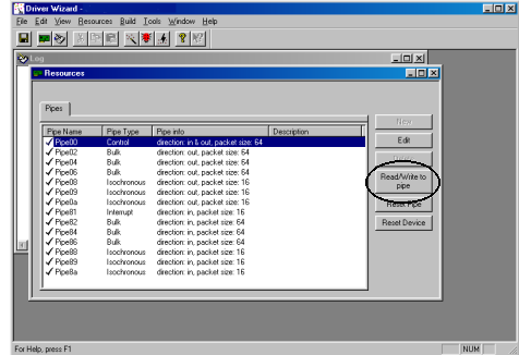
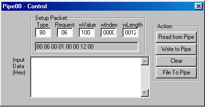
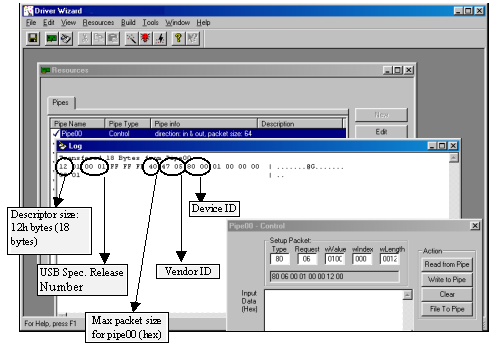
To perform a read or write transaction on the control pipe, you can either use the API generated by DriverWizard for your hardware, or directly call WinDriver WD_UsbTransfer function within your application.
DriverWizard generates the functions below(the functions can be found in the MyDevice_lib.c source file). Fill the setup packet in the BYTE SetupPacket[8] array (an element in the WD_USB_TRANSFER structure) and call these functions to send setup packets on Pipe00 and to retrieve control and status data from the device:
DWORD MY_DEVICE_ReadPipe00(MY_DEVICE_HANDLE hMY_DEVICE,
        PVOID pBuffer, DWORD dwSize, CHAR setupPacket[8])
{
    WD_USB_TRANSFER transfer;
    DWORD i;
    BZERO(transfer);
    transfer.dwPipe = 0x00;
    transfer.dwBytes = dwSize;
    transfer.fRead = TRUE;
    for (i=0; i<8; i++)
        transfer.SetupPacket[i] = setupPacket[i];
    transfer.pBuffer = pBuffer;
    transfer.hDevice = hMY_DEVICE->hDevice;
    WD_UsbTransfer(hMY_DEVICE->hWD, &transfer);
    if (transfer.fOK)
        return transfer.dwBytesTransfered;
    return 0xffffffff;
}
DWORD MY_DEVICE_WritePipe00(MY_DEVICE_HANDLE hMY_DEVICE,
       PVOID pBuffer, DWORD dwSize, CHAR setupPacket[8])
{
    WD_USB_TRANSFER transfer;
    DWORD i;
    BZERO(transfer);
    transfer.dwPipe = 0x00;
    transfer.dwBytes = dwSize;
    for (i=0; i<8; i++)
        transfer.SetupPacket[i] = setupPacket[i];
    transfer.pBuffer = pBuffer;
    transfer.hDevice = hMY_DEVICE->hDevice;
    WD_UsbTransfer(hMY_DEVICE->hWD, &transfer);
    if (transfer.fOK)
        return transfer.dwBytesTransfered;
    return 0xffffffff;
}
For further information regarding WD_UsbTransfer, please refer to Chapter 7 that illustrates the function reference for WinDriver in the WinDriver Manual.
Once your User Mode driver has been written and debugged, you might find that certain modules in your code do not operate fast enough (for example - an interrupt handler or accessing IO mapped regions). If this is the case, try to improve the performance by any one of the two ways suggested in this chapter.
Note that the Kernel PlugIn is not implemented under Windows CE and VxWorks since in these OSes there is no separation between kernel mode and user mode. As such, top performance can be achieved without using the Kernel PlugIn.
Use the checklist below to determine how the performance should be improved in your driver.
The following ``Checklist'' will help you determine how to improve the performance of your driver:
If you do have performance problems:
Identify which part of the code the performance problem is at. Classify and solve the problem according to the table that follows:
| Problem | Solution | |
| #1 | ISA Card - Accessing an IO mapped range on the card | -Try to convert multiple calls to WD_Transfer() to one call
to WD_MultiTransfer()
(See the `Improving performance - Accessing IO mapped regions' section later in this Chapter). -If this does not solve the problem, handle the IO at Kernel Mode, by writing a Kernel PlugIn. (See the Kernel PlugIn related chapters for details) |
| #2 | PCI Card - Accessing an IO mapped range on the card | First, try to change the card from IO mapped to memory mapped
by changing bit 0 of the address space PCI configuration register to 0
and then try the solutions for problem #3. You will probably need to
re-program the
EPROM to initialize BAR0/1/2/3/4/5 registers with different values.
-If this is not possible, try the solutions suggested for problem #1. -If this does not solve the problem, handle the IO at Kernel Mode, by writing a Kernel PlugIn. (See the Kernel PlugIn related chapters for details) |
| Problem | Solution | |
| #3 | Accessing a memory mapped range on the card | -Try to access memory without using
WD_Transfer() by using direct access
to memory mapped regions
(See the `Improving Performance -using direct access to memory mapped regions' section later in this Chapter). -If this does not solve the problem, then there is a hardware design problem. You will not be able to increase performance by using any software design method, or by writing a Kernel PlugIn, or even by writing a full kernel driver. |
| #4 | Interrupt latency. (Missing interrupts, Receiving interrupts too late) | You need to handle the interrupts at
Kernel Mode, by writing a
kernel PlugIn.
(See the Kernel PlugIn related chapters for details) |
| #5 | USB devices: Slow transfer rate | To increase the transfer rate
try to increase
the packet size by
choosing a different
device configuration.
If there is need to do many small transfers, the Kernel-Plugin can be used. |
As a general rule, transfers to memory mapped regions are faster than transfers to I/O mapped regions. The reason is that WinDriver enables the user to directly access the memory mapped regions, without calling the WD_Transfer() function.
After registering a memory mapped region, via WD_CardRegister(), two
results are returned: dwTransAddr and dwUserDirectAddr.
dwTransAddr
should be used as a base address when calling WD_Transfer() to read
or write to the memory region. A more efficient way to perform memory transfers
would be to use dwUserDirectAddr directly as a pointer, and access with it the
memory mapped range. This method enables you to read/write data to your memory-mapped
region without any function calls overhead (i.e. Zero performance degradation).
The only way to transfer data on IO mapped regions is by calling WD_Transfer() function. If a large buffer needs to be transferred, the String (Block) Transfer commands can be used. For example: RP_SBYTE - ReadPort String Byte command will transfer a buffer of Bytes to the IO port. In such a case the function calling overhead is negligible compared to the block transfer time.
In a case where many short transfers are called, the function calling overhead may increase to an extent of overall performance degradation. This may happen if you need to call WD_Transfer() more than 20,000 calls per second.
An example for such a case could be: A block of 1MB of data needs to be transferred Word by Word, where in each word that is transferred, first the LOW byte is transferred to IO port 0x300, then the HIGH byte is transferred to IO port 0x301.
Normally this would mean calling WD_Transfer() 1 million times - Byte 0 to port 0x300, Byte 1 to port 0x301, Byte 2 to port 0x300 Byte 3 to port 0x301 etc (WP_BYTE - Write Port Byte).
A quick way to save 50% of the function call overhead would be to call WD_Transfer() with a WP_SBYTE (Write Port String Byte), with two bytes at a time. First call would transfer Byte0 and Byte1 to ports 0x300 and 0x301,
Second call would transfer Byte2 and Byte3 to ports 0x300 and 0x301 etc. This way, WD_Transfer() will only be called 500,000 times to transfer the block.
The third method would be by preparing an array of 1000 WD_TRANSFER commands. Each command in the array will have a WP_SBYTE command that transfers two bytes at a time. Then you call WD_MultiTransfer() with a pointer to the array of WD_TRANSFER commands. In one call to WD_MultiTransfer() - 2000 bytes of data will be transferred. To transfer the 1MB of data you will need only 500 calls to WD_Transfer(). This is 0.5% of the original calls to WD_Transfer(). The trade off in this case is the memory that is used to set-up the 1000 WD_TRANSFER commands.
This chapter provides you with a brief description of the ``Kernel PlugIn'' feature of WinDriver.
There are some distinct advantages with creating your driver in User Mode.
The advantages of writing a Kernel PlugIn driver over a Kernel Mode driver are:
Using WinDriver's Kernel PlugIn feature, your driver will operate without any degradation.
Not every performance problem requires you to write a Kernel PlugIn. Some performance problems can be solved in the User Mode driver, by better utilization of the features that WinDriver provides.
Chapter 11 guides you in solving your performance issues. This chapter contains a table to help you determine solutions for your driver's performance problems. In some cases a quick User Mode solution is provided, and in other cases, a Kernel Mode PlugIn must be written.
Since you can write your own interrupt handler in the kernel with the WinDriver Kernel PlugIn, you can expect to handle about 100,000 interrupts per sec without missing any one of them.
Using the WinDriver Kernel PlugIn, the developer first develops and debugs the driver in the User Mode with the standard WinDriver tools. After identifying the performance critical parts of the code (such as the interrupt handler, access to I/O mapped memory ranges, or slow data transfer rate through the USB pipes, etc.), the developer can `drop' these parts of code into WinDriver's Kernel PlugIn ( which runs in the Kernel Mode) thereby eliminating calling overhead. This unique feature allows the developer to start with quick and easy development in the User Mode, and progress to performance oriented code only where needed. This unique architecture saves time, and allows absolutely zero performance degradation.
This chapter explains the architectural details of the ``Kernel PlugIn'' feature of WinDriver.
A driver written in the User Mode uses WinDriver's functions(WD_xxx functions) for device access. If a certain function in the User Mode needs to achieve kernel performance (the interrupt handler for example), that function is moved to the WinDriver KernelPlugIn. The code will still work ``as is'' since WinDriver exposes its WD_xxx interface to the Kernel PlugIn as well.
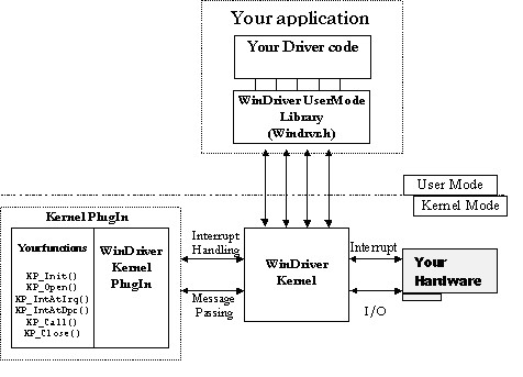
There are two types of interaction between the WinDriver Kernel and the WinDriver Kernel PlugIn. They are:
At the end of your Kernel PlugIn development cycle, you have the following elements to your driver:
The following is a typical event sequence that covers all the functions that you can implement in your Kernel PlugIn(KP):
| Event / Callback | Remarks |
| Event: Windows loads your Kernel PlugIn driver | At boot time, or by dynamic loading, or as instructed by the registry. |
| KP Call-back: Your KP_Init() Kernel PlugIn function is called | KP_Init() informs WinDriver of the name of your KP_Open() routine. WinDriver will call this routine when the applicaton wishes to open your driver (when it calls WD_KernelPlugInOpen()) |
| Event: Your app(User Mode driver) calls WD_KernelPlugInOpen() | |
| KP Call-back: Your KP_Open() routine is called | In your KP_Open() function, you inform WinDriver of the names of all the call-back functions that you have implemented in your KP driver, and initiate the KP driver if needed. |
| Event / Callback | Remarks |
| Event: Your app calls WD_KernelPlugInCall() | Your app calls WD_KernelPlugInCall() to run code in the Kernel Mode(in the KP driver). The app passes a message to the KP driver. The KP driver will select the function to execute according to the message sent. |
| KP Call-back: Your KP_Call() routine is called. | Executes code according to the message passed to it from the User Mode. |
| Event: Your hardware creates an interrupt | |
| KP Call-back: Your KP_IntAtIrql() routine is called. (If the KP interrupts are enabled | KP_IntAtIrql() runs at a high priority, and therefore should do only the basic interrupt handling(such as lowering the HW interrupt signal). If more interrupt processing is needed, it is deferred to the KP_IntAtDpc() function. If your KP_IntAtIrql() function returns a value greater than 0, your KP_IntAtDpc() function is called. |
| Event / Callback | Remarks |
| Event: KP_IntAtIrql() function returns a value greater than 0 | Needs interrupt code to be processed as a deferred procedure call in the kernel |
| KP_Call-back: KP_IntAtDpc() is called | Processes the rest of the interrupt code, but at a lower priority than KP_IntAtIrql |
| Event: KP_IntAtDpc() returns a value greater than 0 | Needs interrupt code to be processed in the User Mode as well |
| KP_Call-back: WD_Intwait() returns. | Execution resumes at your User Mode interrupt handler. |
This chapter takes you through the development cycle of a Kernel PlugIn. It assumes that you have already written and debugged your entire driver code in the User Mode, and have encountered a performance problem.
NOTE: Windows NT/2000 require SYS files for Kernel PlugIn. Windows 95/98/ME need VXD files. SYS files cannot be used on Windows 98/ME as Kernel PlugIn in Version 5.0 and below.
NT DDK can be downloaded (Free) at http://www.microsoft.com/hwdev/ddk/ddk40.htm.
The data exchange function gets the version of the WinDriver kernel module and passes it to the user level. This sample can be a base to implement I/O calls with the Kernel PlugIn.
The interrupt handler implements an interrupt counter. The interrupt handler counts five interrupts and notifies the user mode only on one out of every five incoming interrupts.(more details can be found in windriver\kerplug\kptest\files.txt).
KPTest_com.h contains common definitions such as messages, between the Kernel PlugIn and the User-mode.
The following functions are call-back functions which you will implement in your Kernel PlugIn driver, and which will be called when their `calling' event occurs. For example, KP_Init() is the call-back function which is called when the driver is loaded. Any code that you want to execute upon loading should be in this function.
In KP_Init(), the name of your driver is given. From then on, all of the call-backs which you implement in the kernel will contain your driver's name. For example, if your driver's name is MyDriver, then your `Open' call-back will be called MyDriver_Open(). It is the convention of this reference guide to mark these functions as KP_ functions - i.e. the `Open' function will be written here as KP_Open(), where the KP replaces your driver's name.
In your kernel driver you should implement the following function:
BOOL __cdecl KP_Init(KP_INIT *kpInit);
where KP_INIT is the following structure:
typedef struct {
    DWORD dwVerWD;           // Version of library WD_KP.LIB
    CHAR cDriverName[9];     //  driver name, up to 8 chars.
    KP_FUNC_OPEN funcOpen;   // The KP_Open function
} KP_INIT;
This function is called once, when the driver is loaded. The kpInit structure should be filled out with the KP_Open function and the name of your Kernel PlugIn. (see example in KPTest.c). Note that the name that you choose for your KP driver (by setting it in the kpInit structure), should be the same name as the driver you are creating.
For example, if you are creating a driver called ABC.VXD or ABC.SYS, then you should pass the name ABC in the kpInit structure.
From the KPTest Sample:
BOOL __cdecl KP_Init(KP_INIT *kpInit)
{
    // check if the version of WD_KP.LIB is the same version
    // as WINDRVR.H and WD_KP.H

    if (kpInit->dwVerWD!=WD_VER)
    {
       // you need to re-compile your kernel plugin with
       // the compatible version of WD_KP.LIB, WINDRVR.H
       // and WD_KP.H!
       return FALSE;
    }

    kpInit->funcOpen = KPTest_Open;
    strcpy (kpInit->cDriverName, "KPTest");
    return TRUE;
}
In your Kernel PlugIn file, implement the KP_Open() function, where KP is the name of your KP driver (copied to kpInit->cDriverName in the KP_Init() function.
BOOL __cdecl KP_Open(KP_OPEN_CALL *kpOpenCall, HANDLE hWD, PVOID pOpenData, PVOID *ppDrvContext);
This call-back is called when the User Mode application calls the WD_KernelPlugInOpen() function.
In the KP_Open() function, define the call-backs that you wish to implement in the Kernel PlugIn.
Following is a list of the call-backs which can be implemented:
| Call-back Name | Functionality |
| KP_Close()[16.2.3] | Called when the User Mode application calls the WD_KernelPlugInClose()[16.1.2] Function |
| KP_Call()[16.2.4] | Called when the User Mode application calls the WD_KernelPlugInCall()[16.1.3] function. This function is a message handler for your utility functions. |
| KP_IntEnable()[16.2.5] | Called when the User Mode application calls the WD_IntEnable()[16.1.4] function. This function should contain any initialization needed for your Kernel PlugIn interrupt handling |
| KP_IntDisable()[16.2.6] | Called when the User Mode application calls the WD_IntDisable()[7.18] function. This function should free any memory which was allocated in the KP_IntEnable()[16.2.5] callback. |
| KP_IntAtIrql()[16.2.7] | Called when WinDriver receives an interrupt. This is the function that will handle your interrupt in the Kernel Mode. |
| KP_IntAtDpc()[16.2.8] | Called if the KP_IntAtIrql()[16.2.7] callback has requested deferred handling of the interrupt (by returning with a value of TRUE). |
From the KPTest Sample:
BOOL __cdecl KPTest_Open(KP_OPEN_CALL *kpOpenCall,
              PVOID pOpenData, PVOID *ppDrvContext)
{
    kpOpenCall->funcClose = KPTest_Close;
    kpOpenCall->funcCall = KPTest_Call;
    kpOpenCall->funcIntEnable = KPTest_IntEnable;
    kpOpenCall->funcIntDisable = KPTest_IntDisable;
    kpOpenCall->funcIntAtIrql = KPTest_IntAtIrql;
    kpOpenCall->funcIntAtDpc = KPTest_IntAtDpc;
    *ppDrvContext = NULL; // you can allocate memory here
    return TRUE;
}
Add your specific code inside the call backs routines.
The KPTest directory (\WinDriver\kerplug\KPTest) contains a sample minimal Kernel PlugIn driver which you can compile and execute. Use this sample as your skeletal Kernel PlugIn driver.
This sample builds KPTest.VXD and KPTest.SYS, and KPTest.EXE. The sample demonstrates communication between your application (KPTest.EXE) and your Kernel PlugIn (KPTest.VXD or KPTest.SYS).
The KPTest sample in this directory, is a Kernel PlugIn which implements a ``Get Version'' function, to demonstrate passing data (messages) to/from the Kernel PlugIn. It also implements an interrupt handler in the kernel. This Kernel PlugIn is called by the User Mode driver called KPTest.EXE.
NOTE: To check that you are ready to build a Kernel PlugIn driver, it is recommended to build and run this project first, before continuing to write your own Kernel PlugIn.
Interrupts will be handled by the Kernel PlugIn, if a Kernel PlugIn handle was passed to WD_IntEnable() by the User Mode application when it enabled the interrupt. When WinDriver receives a hardware interrupt, it calls the KP_IntAtIrql() (if Kernel PlugIn interrupts are enabled). In the KPTest sample, the interrupt handler running in the Kernel PlugIn counts 5 interrupts, and notifies the user-mode only of one out of each 5 incoming interrupts. This means that WD_IntWait() (in the user-mode) will return only on one out of 5 incoming interrupts.
If the Kernel PlugIn interrupt handle is NOT enabled, then each incoming interrupt will cause WD_IntWait() to return. See drawing below:
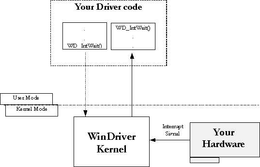
To instruct the interrupts to be handled by the Kernel PlugIn, the Kernel PlugIn handle must be given as a parameter to the WD_IntEnable() function. This enables the Kernel PlugIn interrupt handler.
If the Kernel PlugIn interrupt handler is enabled, then KP_IntAtIrql() will be called on each incoming interrupt. The code in the KP_IntAtIrql() function is executed at IRQL. While this code is running, the system is halted (i.e. there will be no context switch and no lower priority interrupts will be handled). The code in the KP_IntAtIrql() function is limited to the following restrictions:
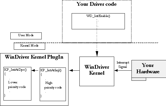
Therefore, the code in KP_IntAtIrql() should be kept to a minimum, while the rest of the code that you want to run in the interrupt handler should be written in the KP_IntAtDpc(), which is called after IRQL finishes. The code in KP_IntAtDpc() is not limited by the above restrictions.
The WinDriver architecture enables calling a Kernel Mode function from the User Mode by passing a message through the WD_KernelPlugInCall() function. The messages are defined by the developer in a header file that is common to both the User Mode and Kernel Mode Plugin parts of the driver. This header file is called KPxxx_COM.H by convention - the corresponding header header file in the KPTest sample is called KPTest_COM.H. Upon receiving the message, WinDriver Kernel PlugIn executes the KP_Call function which maps a function to this message.
In the KPTest sample, the GetVersion function is a simple function which returns an arbitrary integer and string (which simulates your KPTest's version). This function will be called by the Kernel PlugIn, whenever the Kernel PlugIn receives a `GetVersion' message from the KPTest.EXE. You can see the definition of the message KPTEST_MSG_VERSION in the header file KPTEST_COM.H
The KPTest.EXE sends the message using the WD_Kernel PlugInCall() function.
The Kernel PlugIn directory (\windriver\kerplug) contains a sample Kernel PlugIn driver called KP_Test. The sample demonstrates communication between your application (KPTest.EXE) and your Kernel PlugIn (KPTest.VXD or KPTest.SYS).
The easiest way to write a Kernel PlugIn driver is to use this example as the skeletal code for your driver.
The following is a step by step guide to creating your kernel driver. The KPTest sample code will be used to demonstrate the different stages:
In your original User Mode source code, call WD_Kernel PlugInOpen() at the beginning of your code, and WD_KernelPlug InClose() before terminating.
Run compile.bat to compile and link your KP driver.
Copy the relevant file to your drivers directory.
On Win32 Platforms:
Register / Load your driver: The Kernel PlugIn driver is dynamically loadable, and therefore you need not re-boot in order to run your driver.
On all Win32 platforms, you need to run WDREG.EXE to install the driver:
(In the following instructions, NAME stands for your Kernel PlugIn driver name).
On Win95 and WinNT:
Run c:\WinDriver\util\WDREG -name NAME install (in this example run WDREG -name mydrv install) to register and load your driver. For further instructions see chapter 20 that explains how to dynamically load your driver .
On Win98
To install the SYS file, run c:\WinDriver\util\
WDREG -name NAME install(in this example run WDREG -name mydrv install).
To install the VXD file (note the -vxd flag), run c:\WinDriver\util\WDREG -vxd -name NAME install
On Linux
On Solaris
The following functions are the User Mode functions which initiate the Kernel PlugIn's operation, and activate its call-backs.
This function is used to obtain a valid handle for the Kernel PlugIn.
PROTOTYPE
void WD_KernelPlugInOpen(HANDLE hWD, WD_KERNEL_PLUGIN *pKernelPlugIn);
PARAMETERS
(WD_KERNEL_PLUGIN elements)
RETURN VALUE
None
EXAMPLE
// Handle to the KernelPlugIn

WD_KERNEL_PLUGIN kernelPlugIn;

BZERO (kernelPlugIn); // Tells WinDriver which driver to open

kernelPlugIn.pcDriverName = "KPTEST"; // Opens KPTEST.SYS/VXD

WD_KernelPlugInOpen(hWD, &kernelPlugIn);

if (!kernelPlugIn.hKernelPlugIn)
{
 printf ("There was an error loading driver: %s\n",
           kernelPlugIn.pcDriverName);
 return ;
}
printf("Kernel PlugIn opened\n");
Closes the WinDriver Kernel PlugIn handle obtained from WD_KernelPlugInOpen().
PROTOTYPE
void WD_KernelPlugInClose(HANDLE hWD,WD_KERNEL_PLUGIN *pKernelPlugIn);
PARAMETERS
(WD_KERNEL_PLUGIN elements)
hKernelPlugIn - handle of the Kernel PlugIn to close.
RETURN VALUE
EXAMPLE
WD_KernelPlugInClose(hWD, &kernelPlugIn);
Calls a routine in the Kernel PlugIn to be executed.
Calling the WD_KernelPlugInCall() function in the User Mode, calls your KP_Call() callback function in the Kernel Mode. Your KP_Call() function in the Kernel PlugIn will decide what routine to execute according to the message passed to it in the WD_KERNEL_PLUGIN_CALL structure.
PROTOTYPE
void WD_KernelPlugInCall( HANDLE hWD, WD_KERNEL_PLUGIN_CALL *pKernelPlugInCall);
PARAMETERS
(WD_KERNEL_PLUGIN_CALL elements)
RETURN VALUE
None
EXAMPLE
WD_KERNEL_PLUGIN_CALL kpCall;

BZERO (kpCall);    // Prepare the kpCall structure
//from WD_KernelPlugInOpen()
kpCall.hKernelPlugIn = hKernelPlugIn;
// The message to pass to KP_Call(). This will determine
// the action performed in the kernel.
kpCall.dwMessage = MY_DRV_MSG_VERSION;

kpCall.pData = &mydrvVer;   // The data to pass to the call.
WD_KernelPlugInCall(hWD, &kpCall);
If the handle passed to this function is of a Kernel PlugIn, then that Kernel PlugIn will handle all the interrupts.
In this case, upon receiving the interrupt, your Kernel Mode KP_IntAtIrql() function will execute. If this function returns a value greater than 0, then your deferred procedure call, KP_IntAtDpc() , will be called.
PROTOTYPE
void WD_IntEnable(HANDLE hWD,WD_INTERRUPT *pInterrupt);
PARAMETERS
(WD_INTERRUPT elements)
textbfkpCall- information on Kernel PlugIn to install as interrupt handler.
textbfkpCall.hKernelPlugIn- handle of Kernel PlugIn. if zero, then no Kernel PlugIn interrupt handler is installed.
textbfkpCall.dwMessage- message ID to pass to KP_IntEnable() callback.
textbfkpCall.pData- pointer to data to pass to KP_IntEnable() callback.
textbfkpCall.dwResult- value set by KP_IntEnable() callback.
For information about all other parameters of WD_IntEnable(), see the documentation of WD_IntEnable() in Chapter 7 explaining the WinDriver functions.
RETURN VALUE
None
EXAMPLE
WD_INTERRUPT Intrp;

BZERO(Intrp); // from WD_CardRegister()

Intrp.hInterrupt = hInterrupt;

Intrp.Cmd = NULL;

Intrp.dwCmds = 0;

Intrp.dwOptions = 0; // from WD_KernelPlugInOpen()

Intrp.kpCall.hKernelPlugIn = hKernelPlugIn;

WD_IntEnable(hWD, &Intrp);

if (!Intrp.fEnableOk)
 printf ("failed enabling interrupt\n");
The following functions are call-back functions which you will implement in your Kernel PlugIn driver, and which will be called when their `calling' event occurs. For example, KP_Init() is the call-back function which is called when the driver is loaded. Any code that you want to execute upon loading should be in this function.
In KP_Init(), the name of your driver is given, and its call-backs. From then on, all of the call-backs which you implement in the kernel will contain your driver's name. For example, if your driver's name is MyDriver, then your KP_Open call-back may be called MyDriver_Open(). It is the convention of this reference guide to mark these functions as KP_ functions - i.e. the `Open' function will be written here as KP_Open(), where the KP replaces your driver's name.
You must define the KP_Init() function in your code in order to link the Kernel PlugIn driver to the WinDriver.
KP_Init() is called when the driver is loaded. Any code that you want to execute upon loading should be in this function.
PROTOTYPE
BOOL __cdecl KP_Init(KP_INIT *kpInit);
PARAMETERS
kpInit - structure to fill in the address of the KP_Open() callback function.
RETURN VALUE
TRUE if successful. If FALSE, then the Kernel PlugIn driver will be unloaded.
EXAMPLE
BOOL _cdecl KP_Init(KP_INIT *kpInit)

{
  // check if the version of WD_KP.LIB is the same version as
  //WINDRVR.H and WD_KP.H
  if (kpInit->dwVerWD!=WD_VER)
  {

      // you need to re-compile your kernel plugin
      //with the compatible version
      // of WD_KP.LIB,
      // WINDRVR.H and WD_KP.H!
     return FALSE;
  }

  kpInit->funcOpen = KP_Open;
  strcpy (kpInit->cDriverName, "KPTEST");  // until 8 chars
  return TRUE;
}
Called when WD_KernelPlugInOpen() is called from the User Mode. The pDrvContext returned will be passed to rest of the functions.
PROTOTYPE
BOOL __cdecl KP_Open(KP_OPEN_CALL *kpOpenCall, HANDLE hWD, PVOID pOpenData, PVOID *ppDrvContext);
PARAMETERS
kpOpenCall- structure to fill in the addresses of the KP_xxxx() callback functions
hWD- handle of WinDriver that WD_KernelPlugInOpen() was called with.
pOpenData- pointer to data, passed from user-mode.
ppDrvContext- pointer to driver context data with which KP_Close(), KP_Call() and KP_IntEnable() functions will be called. Use this to keep driver specific information.
RETURN VALUE
TRUE if successful. If FALSE, then the call to WD_KernelPlugInOpen() from user-mode will fail.
EXAMPLE
BOOL _cdecl KP_Open(KP_OPEN_CALL *kpOpenCall, HANDLE hWD,
            PVOID pOpenData, PVOID *ppDrvContext)

{
    kpOpenCall->funcClose = KP_Close;
    kpOpenCall->funcCall = KP_Call;
    kpOpenCall->funcIntEnable = KP_IntEnable;
    kpOpenCall->funcIntDisable = KP_IntDisable;
    kpOpenCall->funcIntAtIrql = KP_IntAtIrql;
    kpOpenCall->funcIntAtDpc = KP_IntAtDpc;
    *ppDrvContext = NULL; // you can allocate memory here
    return TRUE;
}
Called when WD_KernelPlugInClose() is called from the User Mode.
PROTOTYPE
void __cdecl KP_Close(PVOID pDrvContext);
PARAMETERS
pDrvContext - driver context data that was set by KP_Open().
RETURN VALUE
None
EXAMPLE
void _cdecl KP_Close(PVOID pDrvContext)
{
 // you can free the memory allocated for pDrvContext here
}
Called when the User Mode application calls the WD_Kernel PlugInCall() function. This function is a message handler for your utility functions.
PROTOTYPE
void __cdecl KP_Call(PVOID pDrvContext, WD_KERNEL_PLUGIN_CALL *kpCall, BOOL fIsKernelMode);
PARAMETERS
RETURN VALUE
None
EXAMPLE
void _cdecl KP_Call(PVOID pDrvContext,
   WD_KERNEL_PLUGIN_CALL *kpCall, BOOL fIsKernelMode)
{
    kpCall->dwResult = MY_DRV_OK;
    switch ( kpCall->dwMessage )
    {
      // in this sample we implement a GetVersion message
    case MY_DRV_MSG_VERSION:
    {
      MY_DRV_VERSION *ver = (MY_DRV_VERSION *)
         kpCall->pData;
      COPY_TO_USER_OR_KERNEL(&ver->dwVer, &dwVer,
          sizeof(DWORD), fIsKernelMode);
      COPY_TO_USER_OR_KERNEL(ver->cVer, "My Driver V1.00",
          sizeof("My Driver V1.00")+1, fIsKernelMode);
      kpCall->dwResult = MY_DRV_OK;
    }
    break;
    // you can implement other messages here
    default:
      kpCall->dwResult = MY_DRV_NO_IMPL_MESSAGE;
    }
}
NOTESThe fIsKernelMode parameter is passed by the Windriver kernel to the KP_Call routine. The user need not do anything about this parameter. But notice how this parameter is passed to the macro COPY_TO_USER_OR_KERNEL - this is required for the macro to function correctly. You may see the implementation of the macro COPY_TO_USER_OR_KERNEL in the header file kpstdlib.h, found under the directory WinDriver\Include of your WinDriver installation.
Called when WD_IntEnable() is called from the User Mode, with a Kernel PlugIn handler specified. The pIntContext will be passed to the rest of the functions that handle interrupts.
This function should contain any initialization needed for your Kernel PlugIn interrupt handling.
PROTOTYPE
BOOL __cdecl KP_IntEnable (PVOID pDrvContext, WD_KERNEL_PLUGIN_CALL *kpCall, PVOID *ppIntContext);
PARAMETERS
pDrvContext- driver context data that was set by KP_Open().
kpCall- structure with information from WD_IntEnable().
kpCall.dwMessage- message ID passed from WD_IntEnable().
kpCall.pData- pointer to data passed from WD_IntEnable().
kpCall.dwResult- value to return to WD_IntEnable().
ppIntContext- pointer to interrupt context data that KP_Int Disable(), KP_IntAtIrql() and KP_IntAtDpc() functions will be called with. Use this to keep interrupt specific information.
RETURN VALUE
Returns TRUE if enable is successful.
EXAMPLE
BOOL _cdecl KP_IntEnable(PVOID pDrvContext,
     WD_KERNEL_PLUGIN_CALL *kpCall, PVOID *ppIntContext)
{

  // you can allocate memory specific for each interrupt
  //in ppIntContext

  *ppIntContext = NULL;

  return TRUE;

}
Called when the User Mode application calls the WD_IntDisable() function. This function should free any memory which was allocated in the KP_IntEnable().
PROTOTYPE
void __cdecl KP_IntDisable(PVOID pIntContext);
PARAMETERS
pIntContext - interrupt context data that was set by KP_Enable().
RETURN VALUE None
EXAMPLE
void _cdecl KP_IntDisable(PVOID pIntContext)
{

  // you can free the interrupt specific
  //memory in pIntContext here

}
This is the function which will run at IRQL if the Kernel PlugIn handle is passed when enabling interrupts.
Code running at IRQL will only be interrupted by higher priority interrupts.
Code running at IRQL is limited by the following restrictions:
The code performed at IRQL should be minimal (e.g. only the code which acknowledges the interrupt), since it is operating at a high priority. The rest of your code should be written at KP_AtDpc(), in which the above restrictions do not apply.
PROTOTYPE
BOOL __cdecl KP_IntAtIrql(PVOID pIntContext, BOOL *pfIsMyInterrupt);
PARAMETERS
pIntContext- interrupt context data that was set by KP_Int Enable().
pfIsMyInterrupt- set this to TRUE, if the interrupt belongs to this driver, or FALSE if not. If you are not sure, it is safest to return FALSE.
RETURN VALUE
Returns TRUE if DPC function is needed for execution.
EXAMPLE
static DWORD G_dwInterruptCount = 0;

BOOL _cdecl KP_IntAtIrql(PVOID pIntContext, BOOL *pfIsMyInterrupt)
{
  // you should check your hardware here to see
  //if the interrupt belongs to you.
  // if in doubt, return FALSE (this is the safest)
  *pfIsMyInterrupt = TRUE;
  // in this example we will schedule a DPC
  //once in every 5 interrupts
  G_dwInterruptCount ++;
  if ((G_dwInterruptCount % 5) == 0 )
    return TRUE;
  return FALSE;

}
This is the Deferred Procedure Call which is executed only if the KP_IntAtIrql() function returned true.
Most of your interrupt handler should be written at DPC.
PROTOTYPE
DWORD __cdecl KP_IntAtDpc(PVOID pIntContext, DWORD dwCount);
PARAMETERS
pIntContext- interrupt context data that was set by KP_Enable().
dwCount- the number of times KP_IntAtIrql() returned TRUE. If dwCount is 1,
then only KP_IntAtIrql() only requested once a DPC. If the value is greater, then KP_IntAtIrql()
has already requested a DPC a few times, but the interval was too short, therefore KP_IntAtDpc() was not called for each one of them.
RETURN VALUE
Returns the number of times to notify user-mode (i.e. return from WD_IntWait()).
EXAMPLE
DWORD _cdecl KP_IntAtDpc(PVOID pIntContext, DWORD dwCount)
{

  // return WD_IntWait as many times as KP_IntAtIrql
  // scheduled KP_IntAtDpc()

  return dwCount;

}
Defines a Kernel PlugIn open command.
Used by WD_KernelPlugInOpen()[16.1.1] and WD_KernelPlugInClose()[16.1.2].
MEMBERS:
| TYPE | NAME | DESCRIPTION |
| DWORD | hKernelPlug In | Handle to Kernel PlugIn |
| TYPE | NAME | DESCRIPTION |
| PCHAR | pcDriverName | Name of Kernel PlugIn driver. Should be no longer than 8 letters. Should not include the VXD or SYS extension. |
| PCHAR | pcDriverPath | The directory and file name in which to look for the KP driver. If NULL, then the driver will be searched for in the default windows system directory, under the name supplied in pcDriverName, with VXD added for Windows-95, or SYS added for Windows-NT |
| PVOID | pOpenData | Data to pass to KP_Open() callback in the Kernel PlugIn |
Used to describe an interrupt.
Used by the following functions: WD_IntEnable()[16.1.4], WD_Int Disable()[7.18], WD_IntWait()[7.19], WD_IntCount()[7.20].
MEMBERS:
| TYPE | NAME | DESCRIPTION |
| WD_KERNEL_ PLUGIN_CALL [17.1.3] | kpCall | The kpCall structure contains the handle to the Kernel PlugIn and other information which should be passed to the Kernel mode interrupt handler when installing it
If the handle is zero, then interrupt is installed without a Kernel PlugIn interrupt handler. |
Contains information about the Kernel PlugIn, which will be used when calling a utility Kernel PlugIn function or when installing an interrupt.
Used by WD_KernelPlugInCall()[16.1.3] and WD_IntEnable()[16.1.4].
MEMBERS:
| TYPE | NAME | DESCRIPTION |
| DWORD | hKernelPlugIn | handle to Kernel PlugIn. |
| DWORD | dwMessage | message ID to pass to KernelPlugIn callback |
| PVOID | pData | pointer to data to pass to Kernel PlugIn callback. |
| DWORD | dwResult | value set by Kernel PlugIn callback, to return back to User Mode. |
The KP_INIT structure is used by your KP_Init()[16.2.1] function in the Kernel PlugIn. Its primary use is for notifying WinDriver what the name of the driver will be, and which Kernel Mode function to call when the application calls WD_KernelPlugInOpen()[16.1.1].
MEMBERS:
| TYPE | NAME | DESCRIPTION |
| DWORD | dwVerWD | Version of WinDriver library WD_KP.LIB. |
| CHAR | cDriver Name[9] | The device driver name, upto 8 chars. |
| KP_FUNC_OPEN | funcOpen | The KP_Open() Kernel Mode function which WinDriver should call when the application calls WD_KernelPlugInOpen() |
This is the structure through which the Kernel PlugIn defines the names of the call-backs which it implements. It is used in the KP_Open() Kernel PlugIn function.
A kernel PlugIn may implement 6 different call-back functions:
| TYPE | NAME | DESCRIPTION |
| KP_FUNC_CLOSE | funcClose | Name of your KP_Close() function in the kernel. |
| KP_FUNC_CALL | funcCall | Name of your KP_Call() function in the kernel. |
| KP_FUNC_INT_ENABLE | funcIntEnable | Name of your KP_IntEnable() function in the kernel. |
| KP_FUNC_INT_DISABLE | funcIntDisable | Name of your KP_IntDisable() function in the kernel. |
| KP_FUNC_INT_AT_IRQL | funcIntAtIrql | Name of your KP_IntAtIrql() function in the kernel. |
| KP_FUNC_INT_AT_DPC | FuncIntAtDpc | Name of your KP_IntAtDpc() function in the kernel. |
The entire WinDriver API can be used when developing drivers in Visual Basic and Delphi.
Using DriverWizard
DriverWizard can be used to diagnose your hardware and verify that it is working properly before you start coding. DriverWizard's automatic source code generator generates code in C and Delphi only. Automatic generation of code in Visual Basic will be supported in later versions of WinDriver.
To create your driver code in C and Delphi, please refer to the ``DriverWizard'' 4 chapter.
Samples
Samples for drivers writtten using the WinDriver API in Delphi or Visual Basic can be found in :
Use these samples as a starting point for your own driver.
Kernel PlugIn
Delphi and Visual Basic cannot be used to create a Kernel PlugIn. Developers using WinDriver with Delphi or VB in User Mode, must use C when writing their Kernel PlugIn.
Creating your Driver
The method of development in Visual Basic is the same as the method in C except for the automatic code generation feature of DriverWizard.
Your work process should be as follows:
To determine and verify the cause of your driver problems ¡ Open the DebugMonitor and set your desired trace level. This will help narrow down your debugging process and lead you in the right direction.
The following may cause WD_Open() to fail:
Action: Run `WDREG.EXE install' (in the \windriver\utildirectory).This will let Windows know how to add WinDriver to the list of device drivers loaded on boot. Also, copy WINDRVR.SYS (for WinNT/2000/98/ME) or WINDRVR.VXD (for Win95/98/ME) to the device drivers directory. A detailed explanation can be found in Chapter 21 that explains how to distribute your driver.
Action: WinDriver will inform you that your evaluation license is over. Please contact Jungo :sales@jungo.com to purchase WinDriver.
Action: Run Your_card_name_DIAG.EXE, (generated by DriverWizard or from the PLX /Galileo /V3 /Altera /AMCC directories), and choose scan-pci bus to check the correct VendorID / DeviceID of your hardware.
Action: Run Your_Card_Name_DIAG.EXE and choose PCI scan. Check that your device returns all the resources needed.
Action: Close all other applications that might be using your device.
WD_CardRegister fails if one of the resources defined in the card cannot be locked.
First, check out what resource (out of all the card's resources) cannot be locked.
Activate the KernelTracer and set the trace mode to trace. This will output all warning and error debug messages. Now, run your application and you will get a printout of the resource that failed.
After finding out the resource that cannot be locked, check out the following:
Is the resource in use by another application? In order for several resource lock requests to the same I/O, Memory or interrupt to succeed, both applications must enable sharing of the resource. This is done by setting fNonSharable = FALSE for every item that can be shared.
When a driver already exists in Windows for your device, you must create an .INF file (DriverWizard automates this process) and install it. For exact instructions, see the sections explaining how to create and install .INF files.
In some operating systems (such as Windows 98), when there is no driver installed for your USB device (Symptom - In DriverWizard's ``Card Information'' screen, the device's physical address is 0x0.), you must create an .inf file (DriverWizard automates this process) and install it. For exact instructions, see the sections explaining how to create and install .INF file.
In some operating systems (such as Windows 98), when there is no device driver
for a new device, the operating system does not allocate resources to the device.
The symptom ¡- When trying to open the card in DriverWizard's ``Card Information''
screen, a message pops-up notifying that no resources were found on card. In
addition, card configuration registers, such as memory `BAR' are zeroed. When
this happens, you need to create and install an INF file for the new card.
For exact instructions,see Chapters 4 and 21 that explain how to create and install a .INF file.
This can occur with level-sensitive interrupt handlers. PCI cards interrupts are usually level sensitive.
Level sensitive interrupts are generated as long as the physical interrupt signal is high. If the interrupt signal is not lowered by the end of the interrupt handling by the kernel, the Windows OS will call the WinDriver kernel interrupt handler again - This will cause the PC to hang!
Acknowledging a level sensitive interrupt is hardware specific. Acknowledging an interrupt means lowering the interrupt level generated by the card. Normally, writing to a register on the PCI card can terminate the interrupt, and lower the interrupt level.
When calling WD_IntEnable() it is possible to give the WinDriver kernel interrupt handler a list of transfer commands (IO and memory read/write commands) to perform upon interrupt, at the kernel level - before WD_IntWait() returns.
These commands can be used to write to the needed register to lower the interrupt level, thereby `re-setting' the interrupt.
Before calling WD_IntEnable(), prepare two transfer command structures (to read the interrupt status and then write the status to lower the level).
 WD_TRANSFER trans[1];

 BZERO (trans);

 trans[0].cmdTrans = WP_DWORD; // Write Port Dword

// address of IO port to write to

 trans[0].dwPort = dwAddr;

 // the data to write to the IO port

 trans[0].Data.Dword = 0;

 Intrp.dwCmds = 1;

 Intrp.Cmd = trans;

 Intrp.dwOptions = INTERRUPT_LEVEL_SENSITIVE;

 WD_IntEnable(hWD, &Intrp);
This will tell WinDriver's kernel to Write to the register at dwAddr a value of `0', upon an interrupt.
The user-mode interrupt handler is the thread waiting on WD_IntWait() - this is your code. Here you only do your normal stuff to handle the interrupt. You do not need to clear the interrupt level since this is already done by the WinDriver kernel , with the transfer command you gave WD_IntEnable().
WD_DMALock() fails to allocate buffer
The efficient method for memory transfer is scatter/gather DMA. If your hardware does not support scatter/gather, you will need to allocate a DMA buffer using WD_DMALock().
WD_DMALock() fails when the Windows OS has run out of contiguous physical memory.
When calling WD_DMALock() with dwOptions = DMA_KERNEL_BUFFER_ALLOC, WinDriver requests the Windows OS for a physical contiguous memory block.
On WinNT you can allocate a few hundred kilobytes by default. If you want to allocate a few megabytes, you will have to reserve memory for it, by setting the following value in the registry:
On Windows NT:
Run REGEDIT.EXE, and access the following key:
HKEY_LOCAL_MACHINE\SYSTEM\CurrentControlSet\Control \SessionManager \MemoryManagement
Increment the value of NonPagesPoolSize.
This change will take place only after re-boot.
On Windows 95:
Win95 does not support contiguous buffer reservation, therefore, the earlier you allocate the buffer, the larger the block you can allocate.
When adding a new driver to the Windows operating system, you must re-boot the system, for the Windows to load your new driver into the system. Dynamic loading enables you to install a new driver to your operating system, without needing to re-boot. WinDriver is a dynamically loadable driver, and provides you with the utility needed to dynamically load the driver you create. You may dynamically load your driver whether you have created a User Mode or a Kernel Mode driver.
A dynamically loadable driver enables your customers to start your application immediately after installing it, without the need to re-boot.
The utility you use to dynamically load and unload your driver is called WDREG.EXE, and is found in \windriver\util\WDREG.EXE.
USAGE: WDREG [-vxd ] [-name <driver name>] [-file <driver file name>]
[[CREATE] [START] [STOP] [DELETE] [INSTALL] [REMOVE]]
WDREG.EXE has 4 basic operations:
For example, to reload WinDriver use:
WDREG STOP START
WDREG.EXE has 2 `shortcut' operations for your convenience:
INSTALL - Creates and starts your driver (same as using WDREG CREATE START).
REMOVE - Unloads your driver from memory, and removes it from the registry so that it does not load on next boot (same as using WDREG STOP DELETE).
You may dynamically load your driver via command line or from within your application as follows:
Dynamically loading your driver via command line:
From the command line, type WDREG INSTALL. This loads the driver into memory, and instructs Windows to load your driver on the next boot.
Dynamically loading your driver in your installation application:
Add the WDREG source code to your installation application.
The full source code for WDREG is found in \windriver\samples\wdreg\
For Linux and Solaris, use the command wdreg <driver name> to load and unload your driver. The parameters are the same as that of the Windows version.
If you have used WinDriver to develop a Kernel PlugIn, you must dynamically load your Kernel PlugIn as well as the WinDriver.
To Dynamically load / unload your Kernel PlugIn driver ([Your driver name].VXD / [Your driver name].SYS):
Use the WDREG command as described above, with the addition of the ''- name'' flag, after which you must add the name of your Kernel PlugIn driver.
For example, to load your Kernel PlugIn driver called KPTest.VXD or KPTest.SYS, use:
WDREG -name KPTest install
(You should not add the .VXD or .SYS extension to your driver name).
WDREG allows you to install your driver in the registry under a different name than the physical file name.
USAGE: WDREG -name [Your new driver name]
-file
[Your original driver name] install
For example, typing the following:
WDREG -name ``Kernel PlugIn Test'' -file KPTest install
Installs the KPTest.VXD or KPTest.SYS driver under a different name.
To dynamically load WinDriver on Linux, execute:
> /sbin/insmod -¡f /lib/modules/misc/windrvr.o
To dynamically unload WinDriver, execute:
> /sbin/rmmod windrvr
In addition, you can use the wdreg script under Linux to install (load) windrvr.o
To dynamically load WinDriver on Solaris, execute:
> /usr/sbin/add_drv -m ``* 0666 root sys'' windrvr
To dynamically unload WinDriver, execute:
> /usr/sbin/rem_drv windrvr
In addition, you can use the wdreg script under Solaris to install (load) windrvr.o
Read this chapter in the final stages of driver development. This chapter guides you in creating your driver package for distribution.
To purchase your WinDriver license, fill in your order form found in \windriver\docs\order.txt, and fax or email it to Jungo (you can find the full details on the order form itself).
Alternatively, you can order WinDriver on-line. See Jungo's WEB site http://www.jungo.com for more details.
When you receive the registered string, you should follow the instructions found under \windriver\redist\register.txt to enable your driver to work with the registered version of the WinDriver kernel. This applies for all OS'es.
In the driver installation script you create, you must copy the following files to the target computer (the system on which you want to install your driver):
NOTE: WINDRVR.SYS can be used on 98/ME. Due to the limitations of 98/ME, it cannot be loaded dynamically but requires a reboot. If a reboot is not acceptable to you, then use WINDRVR.VXD instead.
If you have created a Kernel Plugin
This is done by calling WDREG install. You can add the WDREG source code (found in \windriver\samples\wdreg\wdreg.cpp) to your own installation code, in order to install WinDriver programmatically. The utility WDREG.EXE is found it the UTIL subdirectory under the WinDriver installation.
For Windows 98/ME, WDREG.EXE install installs WINDRVR.SYS and requires a reboot. For a reboot free installation on Windows 98/ME, please install WINDRVR.VXD instead and use the command WDREG -vxd install to install it.
If you have created a WinDriver Kernel PlugIn as well, call ``WDREG.EXE -name [Your driver name] install''. You can add the `WDREG' source code (found in \windriver\samples\wdreg\wdreg.cpp) to your own installation code, in order to install a kernel plugin.
Device information (INF) files are text files, that provide information used by the ``Plug and Play'' mechanism in Windows ME/95/98/2000 to install software that supports a given hardware device. INF files are required for hardware that identifies itself, such as USB and PCI. The INF file includes all necessary information about the device(s) and the files to be installed. When hardware manufactures introduce new products, they must create INF files to explicitly define the resources and files required for each class of device.
In some cases, the .INF file of your specific device is included in the .INF files supplied with the operating system. In other cases, you will need to create a .INF file for your device. DriverWizard can generate an INF specific for your Card/device. The INF is used to tell the OS that the selected device is now handled by WinDriver.
Copy WinDriver Kernel DLL file to the target computer
In the driver installation script you create, you must copy the following files to the target computer (the one you will install your driver on):
For Windows CE hand-held computer installations:
Copy WINDRVR.DLL file to \WINDOWS on your target Windows CE computer.
For Windows CE PC:
Copy WINDRVR.DLL %_FLATRELEASEDIR% and use MAKEIMG.EXE to build a new Windows CE kernel NK.BIN. You should modify PLATFORM.REG and PLATFORM.BIB appropriately before doing this by appending the contents of the supplied files PROJECT_WD.REG and PROJECT_WD.BIB respectively. This process is similar to the process of installing WinDriver CE on a CE PC /ETK installation as described in INSTALLATION AND SETUP.
Add WinDriver to the list of Device Drivers Windows CE loads on boot
For Windows CE hand-held computer installations, please modify the registry according to the entries documented in the file PROJECT_WD.REG. This can be done using the Windows CE Pocket Registry Editor on the hand-held CE computer or by using the Remote CE Registry Editor Tool supplied with the Windows CE Platform SDK. You will need to have Windows CE Services installed on your Windows NT Host System to use the Remote CE Registry Editor Tool. For Windows CE PC/ETK, the required registry entries are made by appending the contents of the file PROJECT_WD.REG to the Windows CE ETK configuration file PROJECT.REG before building the Windows CE image using MAKEIMG.EXE. If you wish to make the WinDriver kernel file a permanent part of the Windows CE kernel NK.BIN, you should append the contents of the file PROJECT_WD.BIB to the Windows CE ETK configuration file PROJECT.BIB as well.
The Linux kernel is continuously under development, and kernel data structures are subject to frequent change. To support such a dynamic development environment and still have kernel stability, the Linux kernel developers decided that kernel modules must be compiled with the identical header files that the kernel itself was compiled with. They enforce this by #include'ing a version number into the kernel header files that is checked against the version number encoded into the kernel. This forces Linux driver developers to facilitate recompilation of their driver based on the target system's kernel version.
You need to distribute these components along with your driver source code or object code. We suggest that you adapt our makefile from the windriver/redist directory to compile and insert the module windrvr.o into the kernel. Note that this makefile calls the wdreg utility shell script that we supply under windriver/util. You should understand how this works and adapt it for your own needs.
Since the kernel plugin module is a kernel module, it also needs to be matched against the active kernel's version number. This means recompilation for the target system. It is advisable to supply the kernel plugin module source code to clients so that they may recompile it. You may also use the same makefile, to build and insert any kernel plugin modules that you distribute with Linux, that you use to recompile and install the WinDriver kernel module.
We suggest that you supply an installation shell script that copies your driver executables to the correct places (perhaps /usr/local/bin), then invoke make or gmake to build and install the windriver kernel module and any kernel plugin modules.
For Solaris, you need to supply the following items to enable the client to enable target installation of your driver:
We suggest that you supply an installation shell script that copies your driver executables to the correct places (perhaps /usr/local/bin), then install the windriver kernel and any kernel plugin modules. You may adapt the utility scripts wdreg and install_windrvr, that we supply under the directory windriver/util for your purpose.
For VxWorks, you need to supply the following items to enable the client to enable target installation of your driver:
In the Tornado II Project's build specification for the VxWorks image, specify windrvr.o and your_drv.out as EXTRA_MODULES under the MACROS tab, and copy these files under the appropriate target directory tree. Rebuild the project and these files are now included in the image and it should work.
You have to use the file usrAppInit.c found under the Tornado II project directory and insert code to call drvrInit() - which is WinDriver's initialization routine - and your driver applications startup routine. Of course, this means you need to rebuild the VxWorks image.
To use the parallel port shell utility (Ppsh) to transfer a Windows CE image from your development workstation to a PC-based hardware development platform, a custom parallel cable is required. This cable requires a DB-25 male connector at both ends, with pins mapped as follows:
To order this cable, please contact:
Redmond Cable
15331 NE 90th Street
Redmond, WA 98052
Telephone: (425) 882-2009
Fax: (425) 883-1430
Part Number: 64355913
Windows 95/98/ME and NT/2000
Windows CE
Linux
Solaris
VxWorks
DRIVERWIZARD GUI
New in Version 2.02
New in Version 2.10
New in Version 2.11
New in Version 2.12
New in Version 3.0
New in Version 3.01
New in Version 3.02
New in Version 3.03
New in Version 4.0
New in Version 4.1
New in Version 4.14
New in Version 4.20
New in Version 4.30
New in version 4.31
New in Version 4.34
New in Version 5.0
Choose the WinDriver product that suits your needs:
Fill in the order form found in `Start | WinDriver | Order Form' on your Windows start menu, and send it back to Jungo via email/fax/mail (see details below).
Your WinDriver package will be sent to you via Fedex / Postal mail. The WinDriver license string will be emailed to you immediately.
E - M A I L
Support: support@jungo.com
Sales: sales@jungo.com
Services: services@jungo.com
P H O N E / F A X
Phone:
USA (Toll-Free): 1-877-514-0537
Worldwide: +972-9-8859365
Fax:
USA (Toll-Free): 1-877-514-0538
Worldwide: +972-9-8859366
W E B:
Jungo http://www.jungo.com
POSTAL A D D R E S S
Jungo Ltd,
P.O.Box 8493,
Netanya 42504,
ISRAEL
WinDriver is licensed per-seat. The WinDriver license allows one developer on a single computer to develop an unlimited number of device drivers, and to freely distribute the created driver without royalties, as outlined in the license agreement below.
SOFTWARE LICENSE AGREEMENT OF WinDriver V5.0
Jungo © 1999-2001
JUNGO (``LICENSOR'') IS WILLING TO LICENSE THE ACCOMPANYING SOFTWARE TO YOU ONLY IF YOU ACCEPT ALL OF THE TERMS IN THIS LICENSE AGREEMENT. PLEASE READ THE TERMS CAREFULLY BEFORE YOU INSTALL THE SOFTWARE, BECAUSE BY INSTALLING THE SOFTWARE YOU ARE AGREEING TO BE BOUND BY THE TERMS OF THIS AGREEMENT. IF YOU DO NOT AGREE TO THESE TERMS, LICENSOR WILL NOT LICENSE THIS SOFTWARE TO YOU, AND IN THAT CASE YOU SHOULD IMMEDIATELY DELETE ALL COPIES OF THIS SOFTWARE YOU HAVE IN ANY FORM.
OWNERSHIP OF THE SOFTWARE
GRANT OF LICENSE
RESTRICTIONS ON USE AND TRANSFER
5a. These files may be distributed only as part of the application you are distributing,
and only if they significantly contribute to the functionality of your application.
5b. You may not distribute the WinDriver header file (WINDRVR.H). You may not
distribute any header file which describes the WinDriver functions, or functions
which call the WinDriver functions and have the same basic functionality as
the WinDriver functions themselves.
5c. You may not modify the distributed files specified in section 5 of this
agreement.
5d. WinDriver may not be used to develop a development product, an API, or any
products which will eventually be part of a development product or environment,
without the written consent of the licensor.
DISCLAIMER OF WARRANTY
Jungo © 1999-2001
Address:
Jungo Ltd,
P.O.Box 8493
Netanya 42504
ISRAEL.
Web site:
http://www.jungo.com
E-mail:
info@jungo.com
Voice:
1-877-514-0537(USA)
+972-9-8859365(Worldwide)
Fax:
1-877-514-0538(USA)
+972-9-8859366(Worldwide)
U.S. GOVERNMENT RESTRICTED RIGHTS